Shanghai Daiyu Education Equipment Manufacturing Co., Ltd.
Language:


|
serial number |
name |
quantity |
Origin |
factory |
|
High voltage section |
||||
|
1 |
Commonly used electrical protection cabinets |
1 |
Shangh* |
Chinese teachings |
|
2 |
10KV vacuum circuit breaker cabinet (handcart type) |
1 |
Shangh* |
Chinese teachings |
|
3 |
10KVCT/PT metering cabinet |
1 |
Shangh* |
Chinese teachings |
|
4 |
Simulated fault generator, simulated high voltage circuit breaker cabinet |
1 |
Shangh* |
Chinese teachings |
|
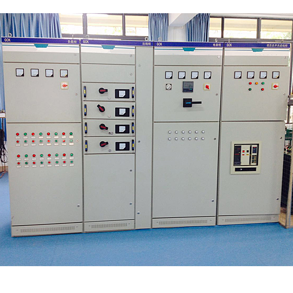
Low voltage section |
||||
|
5 |
Low voltage distribution switch cabinet |
1 |
Shangh* |
Chinese teachings |
|
6 |
Low voltage capacitor compensation cabinet |
1 |
Shangh* |
Chinese teachings |
|
7 |
Drawer type low voltage distribution cabinet |
1 |
Shangh* |
Chinese teachings |
|
8 |
Low voltage load cabinet |
1 |
Shangh* |
Chinese teachings |
1. Det*led technical parameters of commonly used electrical protection cabinets
Cabinet size: 800*600*2200mm industrial grade cabinet
Microcomputer line protection technical parameters
Technical parameters of microcomputer line protection device:
1Rated data
a. Rated power supply voltage: DC or AC 220V or DC 110V
b. Rated AC data:
AC voltage: 100/V, 100V
AC current: 5A or 1A
Zero sequence current: 1A
Rated frequency: 50Hz
c. Thermal stability:
AC voltage circuit: long-term operation 1.2Un
AC current loop: long-term operation 2In
1s 40In
Zero sequence current loop: long-term operation 2A
1s 40A
2Device power consumption
a. AC voltage circuit: each phase is not greater than 0.5VA;
b. AC current circuit: When In=5A, each phase is not more than 1VA;
When In=1A, each phase is not more than 0.5VA;
c. Zero-sequence current loop: no more than 0.5VA;
d. Protect the power circuit: during normal operation, no more than 12W; during protection action, no more than 15W.
3 environmental conditions
a.Ambient temperature:
Working: -25℃~+55℃.
Storage: -25℃~+70℃, relative humidity not greater than 80%, r*nproof and snowproof indoors without acid, alkaline or other corrosive and explosive gases in the surrounding *r; no excitation is applied at the limit value, There should be no irreversible changes in the device, and the device should be able to work normally after the temperature is restored.
b. Relative humidity: The monthly average maximum relative humidity of the wettest month is 90%, while the monthly average minimum temperature of that month is 25°C and there is no condensation on the surface. When the maximum temperature is +40°C, the average maximum humidity does not exceed 50%.
c. Atmospheric pressure: 80kPa~110kPa (relative altitude below 2km).
4 Anti-interference performance
a. Pulse group interference test: It can withstand the pulse group interference test of the frequency of 1MHz and 100kHz attenuated oscillation waves specified in GB/T14598.13-1998 (the first half-wave voltage amplitude common mode is 2.5kV, the differential mode is 1kV).
b. Fast transient interference test: It can withstand the severe level A fast transient interference test specified in Chapter 4 of GB/T14598.10-2007.
c. Radiated electromagnetic field interference test: It can withstand the severe level of radiated electromagnetic field interference test specified in Chapter 4 of GB/T14598.9-2002.
d. Electrostatic discharge test: It can withstand the severe level III electrostatic discharge test specified in 4.1 of GB/T14598.14-1998.
e. Electromagnetic emission test: electromagnetic emission test that can withstand the conducted emission limits specified in 4.1 and the radiated emission limits specified in 4.2 of GB/T14598.16-2002.
f. Power frequency magnetic field immunity test: It can withstand the severe level IV power frequency magnetic field immunity test specified in Chapter 5 of GB/T17626.8-2006.
g. Pulse magnetic field immunity test: It can withstand the pulse magnetic field immunity test with severity level IV specified in Chapter 5 of GB/T17626.9-1998.
h. Damped oscillating magnetic field immunity test: It can withstand the damped oscillating magnetic field immunity test with severity level IV specified in Chapter 5 of GB/T17626.10-1998.
i. Surge immunity test: It can withstand the severe level of surge immunity test specified in Chapter 4 of IEC60255-22-5:2002.
j. Immunity test of conducted disturbance: Immunity test of being able to withstand the conducted disturbance induced by radio frequency fields specified in Chapter 4 of IEC60255-22-6:2001.
k. Power frequency immunity test: It can withstand the power frequency immunity test specified in Chapter 4 of IEC60255-22-7:2003.
5 insulation performance
a. Insulation resistance: between each live conductive circuit and the ground (i.e. the shell or exposed non-live metal parts), between the AC circuit and the DC circuit, between the AC current circuit and the AC voltage circuit, the open circuit voltage is 500V The insulation resistance value tested by the testing instrument should not be less than 100MΩ.
b. Dielectric strength: The device communication circuit and 24V and other weak current input and output terminals can withstand an AC voltage of 50Hz, 500V (effective value) to the ground, and there is no breakdown or flashover phenomenon after a 1-minute inspection; the other live conductive circuits are respectively Between the ground (that is, the shell or exposed non-live metal parts), between the AC circuit and the DC circuit, between the AC current circuit and the AC voltage circuit, it can withstand an AC voltage of 50Hz, 2kV (effective value), and the test lasts for 1 minute. No breakdown or flashover.
c. Impact voltage: The device communication circuit and 24V and other weak current input and output terminals are connected to the ground and can withstand the standard lightning wave impact test of 1kV (peak value); the rem*ning live conductive terminals are connected to the ground respectively, and between the AC loop and the DC loop, the AC Between the current loop and the AC voltage loop, it can withstand the standard lightning wave impact test of 5kV (peak value).
6 Mechanical properties
a. Vibration response: The device can withstand the severity level specified in 4.2.1 of GB/T11287-2000, which is the Level I vibration response test.
b. Impact response: The device can withstand the severity level specified in 4.2.1 of GB/T14537-1993, which is the Level I impact response test.
c. Vibration durability: The device can withstand the severity level specified in 4.2.2 of GB/T11287-2000, which is the Level I vibration durability test.
d. Impact durability: The device can withstand the severity level specified in 4.2.2 of GB/T14537-1993, which is the Level I impact durability test.
e. Collision: The device can withstand the severity level specified in 4.3 of GB/T14537-1993, which is the Level I collision test.
7 Protection setting range and error
a. Fixed value setting range
Current: 0.1In~15In;
Zero sequence current: 0.02A~12A;
AC voltage: 10V~100V;
Delay: 0s~100s.
b. Fixed value error
Current: <±5%;
Voltage: <±5%;
Zero sequence current: The range of 0.02A to 12A does not exceed ±0.01A or ±5%;
Delay error: no more than 50ms or ±2% in the range of 0s~100s.
8Measurement accuracy
a. The measurement error of each analog quantity does not exceed ±0.5% of the rated value;
b. The power measurement error does not exceed ±1% of the rated value;
c. Switch input voltage (DC24V), resolution is not greater than 2ms;
d. Pulse input voltage (DC24V), pulse width not less than 20ms.
9 contact capacity
a. In a DC inductive load circuit with a voltage not greater than 250V, a current not greater than 1A, and a time constant of 5ms±0.75ms, the contact breaking capacity is 50W, and the long-term allowed current is not greater than 5A.
b. In an AC circuit with a voltage not greater than 250V and a current not greater than 2A (cosφ=0.4±0.1), the contact breaking capacity is 250VA, and the long-term allowable current is not greater than 5A.
Commonly used electricity tr*ning projects
Practical tr*ning items:
1. Three-stage current direction protection experiment with low voltage blocking
2. Overcurrent acceleration protection experiment (front acceleration/post acceleration)
3. Overload protection experiment (trip/alarm optional)
4. Zero-sequence current protection experiment (trip/alarm optional)
5. Low voltage protection experiment
6. Low frequency load shedding protection experiment
7. Three-phase primary reclosing experiment
8. Busbar TV disconnection detection and alarm experiment
9. Line TV disconnection detection and alarm experiment
10. Control loop abnormality alarm experiment
11. Jump abnormal alarm experiment
12. Handcart position abnormality alarm experiment
13. Spring no energy storage alarm experiment
2. Det*led technical parameters of 10KV vacuum circuit breaker cabinet (handcart type)
Cabinet size: 2200*800*1500mm industrial grade cabinet
(1) Use environment
1. Ambient temperature: -15℃~+40℃, the d*ly average value is not greater than +35℃.
2. Environmental humidity
D*ly average relative humidity: ≤95%; monthly average relative humidity: ≤90%;
3. Altitude: no more than 1000m. Earthquake intensity: no more than 8 degrees.
4. Install in places without fire, explosion hazard, serious pollution, chemical corrosion and severe vibration.
(2) Basic technical parameters
1. Power supply: three-phase five-wire power supply; power: 3kw.
2. Rated voltage: 12KV; rated frequency: 50Hz;
3. Rated lightning impulse withstand voltage: 75KV (peak value);
4. Rated power frequency withstand voltage for one minute: 42KV (effective value);
5. Rated operating sequence: O-0.3-CO-180s-CO (40KA is O-180s-CO-180s-CO);
6. M*n bus rated current: 630A;
7. Rated short-circuit breaking current: 25KA; rated short-circuit closing current: 630KA (peak value);
8. Rated short circuit duration: 4s; number of openings and interruptions: 50 times;
9. Mechanical life: 20,000 times.
10. Cabinet size: 2200×800×1500 (height×width×depth).
(3) Mechanical characteristic parameters of circuit breaker
1. Contact opening distance: 11±1mm; 2. Contact over-row distance: 3.5±0.5mm;
3. Different periodicity of three levels and closing: ≤2ms;
4. Contact closing bounce time: ≤2ms;
5. Average opening speed: 0.9-1.3m/s (average speed when initial opening is 6mm);
6. Average closing speed: 0.4~0.8m/s; 7. Closing time: ≤100ms;
8. Opening time: ≤50ms; 9. Arcing time: ≤15ms;
(4) Technical parameters of release and locking electromagnet
1. Rated voltage of opening release: -220V, 110V; power: 245W.
2. Rated voltage of closing release: -220V, 110V; power: 245W.
3. Rated voltage of latching electromagnet: -220V, 110V; power: 10W
4. Overcurrent release power: 5AW.
(5) Technical parameters of energy storage motor
Rated voltage -220V, -110V; power: 50W; energy storage time: ≤10m;
(6) Practical tr*ning projects
Manual and remote control closing and opening circuit breaker tr*ning
Secondary control loop principle tr*ning
Practical tr*ning on operating mechanism principles
Circuit breaker disassembly and assembly tr*ning
Switching operation tr*ning
Secondary control loop wiring tr*ning.
3. Det*led technical parameters of 10KVCT/PT metering cabinet
Cabinet size: 2200*800*1000mm industrial grade cabinet
(1) Use environment
1. The altitude does not exceed 3000M;
2. The ambient temperature should not be higher than +40℃ and not lower than -5℃;
3. The relative temperature of the surrounding *r is not greater than 85% (20℃);
4. Install in a place without corrosive gas.
(2) Technical parameters
1. Power supply: three-phase five-wire power supply; power: 3kw;
2. Product standard: GB1207-2006;
3. Product surface creepage distance: meets the earphone pollution level;
4. Load power factor: COSφ=0.8 (lag);
5. Rated voltage ratio:;
6. The grade combination is 0.2/6P, the accurate grade and output capacity are 75VA;
The grade combination is 0.5/6P, the accurate grade and output capacity are 150VA;
7. Residual voltage winding: 100;
8. Thermal limit output capacity: 960VA.
(3) Practical tr*ning projects
Current transformer characteristic testing tr*ning (DC method, AC method)
Voltage transformer characteristic testing tr*ning
Current transformer wiring tr*ning
Voltage transformer wiring tr*ning,
Voltage transformer accuracy measurement tr*ning
Current transformer accuracy measurement tr*ning.
4. Det*led technical parameters of simulated fault generator and simulated high-voltage circuit breaker cabinet
Cabinet size: 600*700*1200mm industrial grade cabinet
(1) Use environment
1. Ambient temperature: -25℃~+55℃;
2. Relative *r humidity: When the temperature is 25°C, the relative humidity can reach 100% in a short time;
3. Altitude: ≤2000m;
4. Not suitable for installation in places with severe vibration, impact, corrosion, or excessive harmonics.
(2) Technical parameters
1. Power supply: three-phase five-wire power supply; power: 3kw;
2. Rated voltage: 380V; rated frequency: 50Hz;
3. Allowable deviation of working voltage: -20% ~ +20%;
4. Rated input voltage analog: 380V, 50Hz;
5. Rated input current analog: 5A, 50Hz;
6. Control physical quantity: reactive power.
(3) Experimental projects:
1. Output various simulated current and voltage fault signals
2. Simulate the closing and opening action signals of the high-voltage circuit breaker
(4) Equipment configuration:
1. Miniature circuit breaker DZ47-63/C10A/3P: 1 piece
2. AC contactor CJX1-16A/AC220V: 1 piece
3. Intermediate relay JZC1-44/AC220V: 1
4. Single-phase voltage regulator TDGC2-200: 10 pieces
5. Single-phase voltage regulator TDGC2-500: 1
6. Single-phase rectifier bridge 60A: 1
7. Single-phase filter capacitor 1500uf: 1 piece
8. Uplifter: 6 pcs.
9. Digital display voltmeter and ammeter: 9 pcs.
5. Det*led technical parameters of low-voltage distribution switch cabinet
Cabinet size: 2200*800*800mm industrial grade cabinet
(1) Use environment
1. Application: power distribution, motor control.
2. Implementation standards: IEC60439\GB7251.1;
3. Ambient temperature: -5℃~+40℃;
4. The ambient relative temperature does not exceed 50% when the ambient temperature is +40°C. At lower temperatures, higher relative temperatures are allowed;
5. Installation location: indoors;
6. Altitude: ≤2000m.
(2) Mechanical data
1. Type of incoming and outgoing wires: cable/bus duct.
2. Cable entry and exit: top/bottom;
3. Wiring form: front of cabinet/rear of cabinet;
4. Protection level: IP330, IP40, IP54;
5. Functional unit isolation form: full isolation or partial isolation;
(3) Horizontal busbar
1. Rated short-time withstand current: 50/80kA;
2. Rated peak withstand current: 105/176kA.
(4) Vertical busbar
1. Rated short-time withstand current: 50kA;
2. Rated peak withstand current: 105kA.
(5) Grounding system: TT, IT, TN-S, TN-CS.
(6) Maximum incoming and outgoing line break: 400A.
(7) Electrical data
1. Power supply: three-phase five-wire power supply; power: 3kw.
2. Rated insulation voltage: to 1000V;
3. Rated working voltage: to 660V;
4. Rated power: 50\60Hz;
5. Rated impulse withstand voltage: 8KV;
6. M*n circuit rated voltage: AC380V, 220V/DC220V
7. Overvoltage level: III;
8. Pollution level: 3; 9. Rated current: 4000A;
10. Horizontal busbar rated current: 4000A;
11. Rated current of vertical busbar: 2000, 1000A
(8) Practical tr*ning projects
M*n electrical schematic tr*ning
Practical tr*ning on the working principle of low voltage circuit breaker
Operational tr*ning
Inspection and m*ntenance tr*ning
Fault analysis and troubleshooting tr*ning
6. Low voltage capacitor compensation cabinet
Cabinet size: 2200*800*800mm industrial grade cabinet
(1) Use environment
1. Ambient temperature: -25℃~+55℃;
2. Relative *r humidity: When the temperature is 25°C, the relative humidity can reach 100% in a short time;
3. Altitude: ≤2000m;
4. Not suitable for installation in places with severe vibration, impact, corrosion, or excessive harmonics.
(2) Technical parameters
1. Power supply: three-phase five-wire power supply; power: 3kw;
2. Rated voltage: 380V; rated frequency: 50Hz;
3. Allowable deviation of working voltage: -20% ~ +20%;
4. Rated input voltage analog: 220V/380V, 50Hz;
5. Rated input current analog: 5A, 50Hz;
6. Control physical quantity: reactive power.
(3) Practical tr*ning projects
Automatic reactive power compensation experiment
Manual reactive power compensation experiment
Reactive power compensation device parameter setting experiment
Voltage and reactive power control experiment
Experiment on the effects of tap adjustment and capacitor switching on voltage and reactive power.
7. Det*led technical parameters of drawer-type low-voltage distribution cabinet
Cabinet size: 2200*800*800mm industrial grade cabinet
(1) Use environment
1. Application: power distribution, motor control.
2. Implementation standards: IEC60439\GB7251.1;
3. Ambient temperature: -5℃~+40℃;
4. The ambient relative temperature does not exceed 50% when the ambient temperature is +40°C. At lower temperatures, higher relative temperatures are allowed;
5. Installation location: indoors;
6. Altitude: ≤2000m.
(2) Mechanical data
1. Type of incoming and outgoing wires: cable/bus duct.
2. Cable entry and exit: top/bottom;
3. Wiring form: front of cabinet/rear of cabinet;
4. Protection level: IP330, IP40, IP54;
5. Functional unit isolation form: full isolation or partial isolation;
(3) Horizontal busbar
1. Rated short-time withstand current: 50/80kA;
2. Rated peak withstand current: 105/176kA.
(4) Vertical busbar
1. Rated short-time withstand current: 50kA;
2. Rated peak withstand current: 105kA.
(5) Grounding system: TT, IT, TN-S, TN-CS.
(6) Maximum incoming and outgoing line break: 400A.
(7) Electrical data
1. Power supply: three-phase five-wire power supply; power: 3kw.
2. Rated insulation voltage: to 1000V;
3. Rated working voltage: to 660V;
4. Rated power: 50\60Hz;
5. Rated impulse withstand voltage: 8KV;
6. M*n circuit rated voltage: AC380V, 220V/DC220V
7. Overvoltage level: III;
8. Pollution level: 3; 9. Rated current: 4000A;
10. Horizontal busbar rated current: 4000A;
11. Rated current of vertical busbar: 2000, 1000A
(8) Practical tr*ning projects
M*n electrical schematic tr*ning
Practical tr*ning on the working principle of imported low-voltage circuit breakers
Operational tr*ning
Inspection and m*ntenance tr*ning
Fault analysis and troubleshooting tr*ning
One and two wiring tr*ning.
8. Det*led technical parameters of low voltage load cabinet
Cabinet size: 2200*800*800mm industrial grade cabinet
(1) Use environment
1. Ambient temperature: -25℃~+55℃;
2. Relative *r humidity: When the temperature is 25°C, the relative humidity can reach 100% in a short time;
3. Altitude: ≤2000m;
4. Not suitable for installation in places with severe vibration, impact, corrosion, or excessive harmonics.
(2) Technical parameters
1. Power supply: three-phase five-wire power supply; power: 10kw.
2. Rated insulation voltage: to 1000V;
3. Rated working voltage: to 660V;
4. Rated power: 50/60Hz;
5. Rated impulse withstand voltage: 1KV;
6. M*n circuit rated voltage: AC380V/220V
7. Overvoltage level: III;
8. Pollution level: 3;
9. Rated current: 400A;
10. Horizontal busbar rated current: 400A;
(3) Experimental projects:
Simulate resistive, capacitive and inductive loads
Commissioning and withdrawal of active/reactive equipment
Conduct reactive power compensation experiments with the reactive power compensation cabinet
On-site reactive power compensation tr*ning
Power factor meter wiring experiment
Hot-selling product: Electrician tr*ning bench
 Wechat scan code follow us

24-hour hotline+86 18916464525

Phone18916464525
ADD:Factory 414, District A, No. 6, Chongnan Road, Songjiang Science and Technology Park, Shanghai ICP: Sitemap