Shanghai Daiyu Education Equipment Manufacturing Co., Ltd.
Language:


1.Core board hardware parameters
1.1CPU: OMAP3530 DCUS, 600-MHz ARM Cortex-A8 Core 412-MHz TMS320C64x+ DSP Core, integrated memory for ARM CPU (16kB I-Cache, 16kB D-Cache, 256kB L2) and on-chip storage (64kB SRAM, 112kB ROM )
1.2DDR RAM: 256MB DDR RAM MT29C2G48MAKLCJA-6IT
1.3FLASH: 256MB NAND FLASH MT29C2G48MAKLCJA-6IT
1.4 Power management: independent power management chip TPS65930
1.5LDO: equipped with LDO
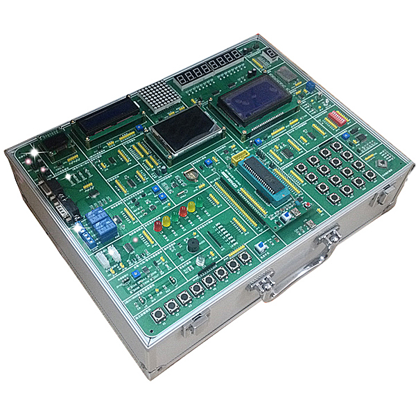
2. Baseboard hardware parameters
2.1FPGA: XC3S250E-P208 is used to control logic and expand serial ports, and assign addresses to corresponding devices.
2.2 Ethernet: 1 10/100M adaptive Ethernet controller DM9000A
2.3LED: 12 GPIO-controlled LED working status indicators: 6 located on the core board and 6 located on the base board
2.4 Audio: Standard AC97 audio controller small three-core interface + MIC head TPS65930
2.5 Reset: Isolate internal and external reset signals to increase reset reliability TC7SH08FU
2.6UART: A total of 7 UART channels: 3 channels are built-in with the processor, 4 channels are externally expanded by FPGA, 1 channel is connected to the infrared, 2 channels are connected to the expansion interface, and 4 channels are connected to the DB9 connector.
2.7RTC: Independent RTC 1220 battery powered
2.87-inch LCD: 7-inch 24-bit LCD screen with resistive touch screen 16:9 display, resolution: 800 × 480 connected to DSS (AT070TN83)
2.91.8-inch LCD: 1.8-inch TFT LCD, resolution 128*160, mounted on the GPMC bus (HX8310)
2.10 Touch screen interface: SPI extends the touch screen interface, and the touch screen is matched with the 7-inch screen (TSC2046)
2.11TV-OUT: One S-VIDEO interface, mixed video signal
2.12BUFFER: Has a bus buffer for easy isolation and replacement
2.13DVI: One DVI interface, which can output DVI-D high-definition signal (TFP410) with a resolution of 1280x720 and a code rate of 30fps.
2.14WIFI+BT: WIFI+BT+FM three-in-one module expands WG7310-00 module (WL1271) through SDIO
2.15IrDA: Infrared sensor , infrared transmission (HSDL-3600#017)
2.16 Power supply: external DC power supply 12V or 5V power supply, 5A or 3A power supply
2.17 Power interface: Reserved 3V, 5V, 12V power interfaces
2.18IIC interface: 2 IIC and one IIC expansion interface
2.19SDIO interface: external WIFI and Bluetooth
2.20SPI interface: 2-way SPI expansion interface
2.21 digital tube and LED dot matrix: 4 digital tubes, 1 16x16 dot matrix
2.22 full keyboard: Expandable special keyboard for this computer through USB port
2.23 matrix keyboard: 4x5 independent matrix keyboard
2.24 camera: High-quality camera OV3640 300W pixels, which can realize H.264 video real-time encoding and decoding, 30 frames per second, can be used for taking pictures and video calls
2.25SD/MMC: 1 high-speed SD/MMC card interface
2.26JTAG: 1 channel 20PIN ARM JTAG, 1 channel 10PIN FPGA JTAG
2.27 Temperature sensor: LM75
2.28USB HOST: 4 USB HOST high-speed interfaces, supporting USB mouse, keyboard, Bluetooth, U disk, camera and wireless network card. Expand the two-level HUB with a total of 7 av*lable USBs (FE1.1)
2.29USB OTG: Mini USB AB interface one
2.30AD: 4 channels AD: 3 channels 16bit AD7792, 1 channel 8bit ADS1110
2.31 buttons: 6 GPIO control buttons, preset functions, user-definable functions, 4 fixed function buttons
2.32EEPROM: 16K (24C16)
2.33 DIP switch: 1 group (32 bits)
2.34 power supply: external 12V/3A DC power supply, internal LDO voltage stabilization
2.35 bus expansion interface: 192pin European socket expansion, bus, serial port, IIC, GPIO, etc., supports the following optional expansion modules (optional):
(1) Fingerprint expansion module
(2) IEEE802.15.4 Zigbee expansion module
(3) FM module
2.36SENSOR MODULE (optional):
Expandable: 6-in-1 sensor expansion module (temperature, humidity, photoelectric sensor, pressure sensor, proximity switch, photoelectric switch)
3.Experimental requirements
3.1Win CE experiment
Experiment 1: Set up WINCE6.0 development environment
Experiment 2: Establish WIN CE6.0 platform and export SDK
Experiment 3: Programming WINDOWS CE
Experiment 4: Establish the connection between the host machine and the experimental box
Experiment 5 HelloWorld experiment under VS2005
Experiment 6 window experiment
Experiment 7 Dialog dialog box experiment
Experiment eight buzzer experiment
Experiment 9 1.8-inch LCD screen experiment
Experiment 10 LEDARY lattice experiment
Experiment 11 Eight-segment digital tube experiment
Experiment 12 LED experiment
Experiment 13 DIP switch experiment
Experiment 14 IIC bus-temperature sensor test
Experiment 15 IIC bus-EEPROM experiment
Experiment 16AD experiment
Experiment 17 RS232 communication experiment
Experiment 18 RS485 communication experiment
Experiment 19 6-in-1 sensor experiment (requires 6-in-1 expansion module)
Experiment 20 camera collection experiment
Experiment 21 Matrix Keyboard Experiment
Experiment 22 SIXKEY Interruption Experiment
Experiment 23 Fingerprint experiment (requires fingerprint module)
Experiment 24 Zigbee experiment (requires Zigbee module)
3.2LINUX experiment
Experiment 1 Install VMware Workstation software
Experiment 2: Install UBUNTU operating system
Experiment 3: Establishing a host cross-compilation development environment
Experiment 4 Install and configure minicom
Experiment 5 Configuring HyperTerminal
Experiment 6 Configuring NFS Service
Experiment 7 Configuring TFTP
Experiment 8 Compile x-loader
Experiment 9 Compiling U-Boot
Experiment 10 Compile KERNEL
Experiment 11 Compile POMAP
Experiment 12 Deploy file system
Experiment 13: Connecting to the target board
Experiment 14: Format SD card
Experiment 15: Start the system through SD card
Experiment 16: Burn image to NAND FLASH through SD card
Experiment 17: Burn the image to NAND FLASH through TFTP
Experiment 18 starts via NFS
Experiment 19 Simple Procedure
Experiment Twenty HelloWorld Experiment
Experiment 21 GPIO experiment SWITCH
Experiment 22 IIC experiment (reading and writing EEPROM)
Experiment 23 SPI experiment (AD7792)
Experiment 24 LED dot matrix experiment
Experiment 25 digital tube experiment
Experiment twenty-six LED experiment
Experiment twenty-seven DSP experiment
Experiment twenty-eight button interruption experiment
Experiment twenty-nine touch screen experiment
Experiment 30 QT experiment
3.3Android experiment
Experiment 1: Establishing JDK, an application development environment under Windows
Experiment 2 Install Eclipse
Experiment 3 Install and configure ADT and Android SDK
Experiment 4 Android emulator operation
Experiment 5 Android Hello application development
Experiment 6: Install VMware Workstation virtual machine software
Experiment 8 Installing Ubuntu system in a virtual machine
Experiment 9: Establishing a host development environment
Experiment 10 Install JDK1.5
Experiment 11 configure minicom
Experiment 12: Configuring HyperTerminal
Experiment 12 Configuring TFTP
Experiment 13 Compile U-boot
Experiment 14 Compile x-loader
Experiment 15: Compile LINUX kernel
Experiment 16: Compile Android and create file system
Experiment 17 SD mode startup
Experiment 18 Android application technical support and service
Provide hardware schematic diagrams, hardware PCB diagrams, and software design resources.
Hot-selling product: Electrician tr*ning bench
 Wechat scan code follow us

24-hour hotline+86 18916464525

Phone18916464525
ADD:Factory 414, District A, No. 6, Chongnan Road, Songjiang Science and Technology Park, Shanghai ICP: Sitemap