Shanghai Daiyu Education Equipment Manufacturing Co., Ltd.
Language:


The electrical and electronic electric mop plc microcontroller sensor tr*ning and assessment device is a product developed by our company in accordance with the requirements of the Ministry of Education's "Revitalization of the 21st Century Vocational Education Curriculum Reform and Teaching Materials Construction Plan" and in accordance with the teaching and tr*ning requirements of vocational education. It has a reasonable structure. The components for practical tr*ning are hanging box type, making it easy to add or expand practical tr*ning items, covering the tr*ning outlines of courses such as "Circuit Analysis", "Basics of Electrical Engineering", "Electrical Engineering", " Motor Control", "Relay Contact Control" and "Electronic Technology" Requirements, it is suitable for the new construction, expansion and upgrading of laboratories in higher vocational colleges, technical schools, vocational schools and other laboratories , providing ideal tr*ning equipment for schools to quickly open practical tr*ning courses.
1. Technical performance
1. Input power: three-phase four-wire (or three-phase five-wire) ~ 380V ± 5% 50Hz
2. Temperature: -10℃ ~ +40℃, relative humidity <85% (25℃)
3. Device Capacity: <1.5KVA
4. Weight: 120Kg
5. Dimensions: 1600mm×700mm×1500mm
2. Device structure
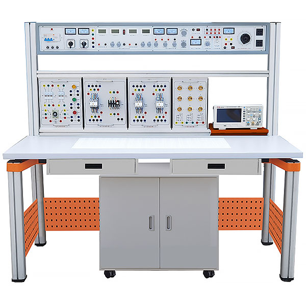
The device consists of m*n chassis, experimental table, tr*ning hanging box, independently packaged tr*ning circuit module, mobile low cabinet, and oscilloscope stand , student stools, etc. The tr*ning device bracket and the tr*ning table can be combined and disassembled. The bracket is integrated with the table legs and has an aluminum alloy structure. The tr*ning hanging box and each experimental module can be freely combined and placed according to experimental needs.
(1) M*n chassis
The m*n chassis is made of iron with a double-layer matt dense spray-p*nted structure and an aluminum panel. It provides AC power supply, DC regulated power supply, constant current source, function signal generator, test instruments and practical tr*ning. Devices, etc.
The specific functions are as follows:
1. Control and AC power supply part
(1) Provides three-phase fixed 380V AC power supply, current-type voltage-type leakage switch protection, and measures the three-phase output line voltage through the transfer switch.
(2) Provide a single-phase 0~250V/2A continuously adjustable AC power supply (equipped with a 0.5KVA single-phase voltage regulator). At the same time, a set of 0-240V continuously adjustable DC power supply can be obt*ned through the rectification link, with a meter indicating the output voltage value.
(3) Provide 3V, 6V, 9V, 12V, 15V, 20V, 24V low-voltage AC power supply, current 1.5A.
(4) Provide 3 ~220V sockets to provide working power for external instruments.
(5) Fluorescent lamp lead port.
(6) Equipped with a set of 220V/30W fluorescent tubes and brackets for practical tr*ning. A set of 220V/30W fluorescent tubes and brackets are placed at the bottom of the m*n chassis, which takes up no space and facilitates observation of tr*ning conditions.
2. DC power supply part
(1) Dual-channel constant current regulated power supply, the output voltage of both channels is 0-30V, and the built-in relay automatically shifts gears. The multi-turn potentiometer is continuously adjusted and easy to use. The maximum output current is 1.5A, with preset current-limiting protection function. The output has 0.5-level digital ammeter and voltmeter indication, voltage stability is 10-2, load stability is 10-2, and ripple voltage is 5mv.
(2) Low-voltage DC regulated power supply: ±12V, ±5V, current 0.5A, indicated by a meter.
3. Power output function generator: uses direct digital frequency synthesis (DDS) to generate high-precision sine waves, square waves and triangle waves. Use large-screen LCD to display output frequency, waveform, and attenuation value.
| Sine wave output amplitude | ≥10V |
| Output impedance | 50Ω |
| Distortion | <1% (0.1HZ-- 1KHz) |
| Frequency Range | 0.1HZ~3MHz, use the keyboard to directly input numbers to set the frequency |
| Output amplitude | Potentiometer adjustment, sine wave output with 20db, 40db attenuation |
| square wave duty cycle | Adjustable, adjustment range: 1%-99% adjustment; square wave and triangle wave adopt TTL level output. |
| Frequency meter** measuring range | 100MHz, automatic shifting |
4. Instrument part
4.1, 1 smart AC voltmeter: measuring range: 0-1000V, set to four ranges of 1V/10V/100V/1000V, six-digit digital display of the measurement value. The instrument adopts modern technology, has digital Chinese display, is intelligent, digital, and has host computer communication functions. The instrument can be set and operated through buttons, ranging from manual to automatic mode switching, calibration, zero adjustment, filtering series setting, communication address setting, Over-range automatic alarm prompts and protection functions. The hardware part has strong integrity and high integration. It is made using surface-mount technology, industrial plastic shell, and panel embedded installation. It is stable in use and easy to replace, upgrade and m*nt*n.
4.2. 1 smart AC ammeter: measurement range: 0-5A, set to three ranges of 10mA/500mA/5A, six-digit digital display of the measurement value. The instrument adopts modern technology, has digital Chinese display, is intelligent, digital, and has host computer communication functions. The instrument can be set and operated through buttons, ranging from manual to automatic mode switching, calibration, zero adjustment, filtering series setting, communication address setting, Over-range automatic alarm prompts and protection functions. The hardware part has strong integrity and high integration. It is made using surface-mount technology, industrial plastic shell, and panel embedded installation. It is stable in use and easy to replace, upgrade and m*nt*n.
4.3. 1 smart DC voltmeter: Measuring range: 0-1000V, set to four ranges of 1V/10V/100V/1000V, six-digit digital display of the measurement value. The instrument adopts modern technology, has digital Chinese display, is intelligent, digital, and has host computer communication functions. The instrument can be set and operated through buttons, ranging from manual to automatic mode switching, calibration, zero adjustment, filtering series setting, communication address setting, Over-range automatic alarm prompts and protection functions. The hardware part has strong integrity and high integration. It is made using surface-mount technology, industrial plastic shell, and panel embedded installation. It is stable in use and easy to replace, upgrade and m*nt*n.
4.4. 1 smart DC ammeter: Measuring range: 0-5A, set to three ranges of 10mA/500mA/5A, six-digit digital display of the measurement value. The instrument adopts modern technology, has digital Chinese display, is intelligent, digital, and has host computer communication functions. The instrument can be set and operated through buttons, ranging from manual to automatic mode switching, calibration, zero adjustment, filtering series setting, communication address setting, Over-range automatic alarm prompts and protection functions. The hardware part has strong integrity and high integration. It is made using surface-mount technology, industrial plastic shell, and panel embedded installation. It is stable in use and easy to replace, upgrade and m*nt*n.
4.5. 1 multi-functional AC parameter table: power measurement accuracy is 0.5, power factor measurement range is 0.3-1.0, voltage and current range is 450V and 5A. Six-digit digital display of active power, reactive power, total power, power factor, voltage, current, load type, load type: L, R, C. The instrument adopts modern technology, has digital Chinese display, is intelligent, digital, and has host computer communication functions. The instrument can be set and operated through buttons, ranging from manual to automatic mode switching, calibration, zero adjustment, filtering series setting, communication address setting, Over-range automatic alarm prompts and protection functions. The hardware part has strong integrity and high integration. It is made using surface-mount technology, industrial plastic shell, and panel embedded installation. It is stable in use and easy to replace, upgrade and m*nt*n.
(2) Electrician tr*ning hanging box
1. DG0221 circuit basic module (1) Provides resistance, inductance, capacitance, circuit basic experiment modules and fault buttons (3), etc., to complete the superposition theorem, Kirchhoff's law, Thevenin's theorem, Norton's theorem, equivalent transformation of voltage source and current source, research on the transition process of first-order and second-order circuits, research on RLC series resonant circuit and other experiments.
2. DG0222 circuit basic module (2) provides various power resistors, light bulbs (12V/0.1A), voltage regulator tubes (2CW51), diodes, potentiometers (one each of 1k/2W, 10k/2W, and 100k), and resistors Box (0~9Ω/2W, 0~90Ω/2W, 0~900Ω/2W, 0~9000Ω/2W, one set each), etc.
3. DG0223 AC circuit module (1) provides an iron core transformer (50VA, 36V/220V), current socket, etc. The primary and secondary sides are equipped with fuses and current sockets, which facilitates testing and can reliably protect the transformer from damage.
4. DG0224 AC circuit module (2) Provides 0.22uF/500V, 0.47uF/500V, 1uF/500V (three pieces), 2.2uF/500V, 4.7uF/500V high-voltage capacitors, ballasts, starters, etc., high-voltage The capacitor can be controlled by a toggle switch to complete the fluorescent lamp circuit connection and power factor improvement experiments.
5. DG0225 AC circuit module (3) provides four sets of loads and four sets of independent current sockets. Each load group consists of two independent incandescent lamp screw sockets (each group is equipped with a switch and a current socket). Can plug in eight incandescent lamps below 60W. Able to complete three-phase AC circuit experiments.
(3) Electrical control tr*ning hanging box: aluminum panel, back cover made of die-molded aluminum profiles and injection-molded plastic parts. The electrical component wiring points have all been led to safety sockets, making experimental wiring convenient, safe and fast.
1. Electrical control tr*ning hanging box 1: 2 AC contactors
2. Electrical control tr*ning hanging box 2: 1 AC contactor, 1 thermal relay
3. Electrical control tr*ning hanging box 3: 1 time relay, Buttons red, yellow, and green
4. Electrical control tr*ning hanging box 4: 4 travel switches, 1 AC contactor, 1 button, 2 resistors (510Ω/25W)
(4) 2 three-intersection motors: 380V/ 180W, aluminum housing.
(5) Magnetic electronics, microcontroller, and sensor tr*ning modules.
The tr*ning circuit board module is composed of a PCB panel and a magnetic fixing mechanism. The tr*ning circuit board is equipped with parameter test points and fault setting switches. The tr*ning circuit board PCB panel surface Refreshing, practical circuits and symbols have clear lines, the surface is wear-resistant, and components are easy to replace; the component circuit symbols marked on the panel adopt national standards, and have the characteristics of compact overall structure, beautiful appearance, simple installation, and convenient use and storage. The wire jack adopts an anti-rotation socket, and the wire is equipped with an elastic plug that can be plugged on the module to ensure reliable connection for various tr*nings; during tr*ning, the corresponding tr*ning circuit board can be selected according to the tr*ning content and skill tr*ning needs. Modules etc.
The tr*ning circuit board module is equipped with a public tr*ning base. The public tr*ning base is matched with the magnetic fixing mechanism of the tr*ning circuit board module. During tr*ning, you only need to place the tr*ning circuit board module on the public tr*ning base. It can be firmly attached to the public tr*ning base and then do the required tr*ning projects. The structure of the public tr*ning base is in line with ergonomic design, and the tr*ning operation is convenient, scientific and reasonable.
1. Analog circuit tr*ning module
① The transistor amplifier circuit
module has a power supply indication and power supply unit, and a transistor amplifier unit module circuit, which can complete single-tube amplifier circuit experiments, two-stage amplifier circuit experiments, negative feedback amplifier circuit experiments, etc. , the experimental circuit can complete the construction of different experimental circuits by switching the switch. It is also equipped with a dedicated waveform test ring to facilitate waveform measurement.
② The second
module of the transistor amplifier circuit has a power supply indication and power supply unit, a differential amplifier circuit, and a field effect tube amplifier circuit. It can complete experiments such as field effect tube amplifier circuit experiments and differential amplifiers. The experimental circuit can complete different tasks by switching the switch. Construction of experimental circuit. It is also equipped with a dedicated waveform test ring to facilitate waveform measurement.
③ The waveform generation circuit
module has a power supply indication and power supply unit, and a waveform generation circuit, which can complete RC sine wave oscillator experiments, LC sine wave oscillator and other experimental contents. The experimental circuit can be switched by switching to complete the construction of different experimental circuits. It is also equipped with a dedicated waveform test ring to facilitate waveform measurement.
④ The integrated operational amplifier circuit
module has power supply indication and power supply unit and integrated amplifier circuit experimental content. At the same time, the module also provides common components such as resistors, capacitors, and diodes required in various experiments to meet experimental needs.
⑤ The power amplifier circuit
module is equipped with power supply indication, power supply unit, and power amplifier circuit, which can complete experimental contents such as OTL power amplifier circuit and integrated power amplifier circuit. The experimental circuit can be completed by switching the switch to build different experimental circuits. It is also equipped with a dedicated waveform test ring to facilitate waveform measurement.
⑥ The DC stabilized power supply circuit
module has power supply indication and power supply unit, rectifier circuit, input filter, output filter, adjustable integrated voltage stabilization, diode voltage stabilization, transistor series voltage stabilization, thyristor controllable rectification, and fixed integrated voltage stabilization circuit , can complete various voltage stabilizing circuit experimental contents.
⑦ Capacitive three-point LC oscillator circuit
with DC +12V power supply, independent power switch; Schiller and Clapp circuit switching test, the static operating point is adjustable, and the capacitance value of the oscillation circuit is optional. Familiar with the influence of static operating point, coupling capacitance, feedback coefficient and equivalent Q value on the oscillator amplitude and frequency
⑧ Integrated multiplier amplitude modulation circuit with
DC ±12V power supply and independent power switch; realizes AM, DSB and SSB three amplitude modulation waves , observe the spectral characteristics of three types of amplitude modulated waves, and study the relationship between the modulated wave, the modulated signal, and the carrier wave.
⑨ The amplitude demodulator (envelope detection) circuit
is powered by DC +12V and has an independent power switch; it realizes coherent detection of amplitude modulation signals. Understand the concept that synchronous detectors can demodulate various AM waves, DSB waves and SSB waves
⑩ Amplitude demodulator (synchronous detection) circuit
DC +12V power supply, independent power switch; suitable for demodulating large signal levels (commonly known as large signal) AM wave. It has the advantages of simple circuit, good detection linearity and easy implementation.
11 Varactor diode frequency modulator circuit
DC +12V power supply, independent power switch; realize static modulation and dynamic modulation, master the method of using varactor diode frequency modulation oscillator to realize FM;
12 Capacitive coupling loop phase frequency discriminator circuit
DC +12V power supply, Independent power switch; has two methods of phase frequency identification and slope frequency identification. Expl*n the working principle of the capacitive coupling loop phase frequency discriminator, and be familiar with the influence of primary and secondary loop capacitance and coupling capacitance on the operation of the capacitive coupling loop phase frequency discriminator.
13 Phase-locked loop frequency modulator circuit
DC +12V power supply, independent power switch; frequency modulator implemented using 4046, master the principles and methods of frequency modulation using 4046 integrated circuits.
14 Phase-locked loop frequency discriminator circuit
uses DC +12V power supply and independent power switch; uses 4046 to realize the frequency demodulator. Understand the principle of using 4046 integrated circuit to realize frequency demodulation and deepen the understanding of the working principle of phase-locked loop.
15 Load module
1. Provides a 12V/5W light bulb load;
2. Provides a 200 ohm/2W power resistor;
3. Provides a 12V/1.2W DC motor load;
2. Digital circuit tr*ning module
① DIP expansion circuit
template Equipped with power supply indication and power supply unit, and 2 sets of 14-pin locking sockets, it is convenient to expand the use of various digital chips and expand practical tr*ning content.
② The second
template of the DIP expansion circuit is equipped with power supply indication and power supply unit, a set of 20-pin locking sockets, and military round-hole type direct plug-in IC sockets, which facilitates the expansion of the use of various digital chips and expands the tr*ning content.
③ The three
templates of the DIP expansion circuit are equipped with power supply indication and power supply units, two 400-hole breadboards, and provide a 16-way single-row socket to gold-plated step socket circuit, which is convenient for expanding the use of various digital chips, freely building experimental circuits, and expanding practical tr*ning content.
④ The logic level output circuit
module has a power supply indication and power supply unit, 2 sets of TTL three-state output circuit units (with three-color indicator lights), 16-channel TTL level output units (with three-color indicator lights), 16-channel with Drives the TTL level indication unit (three-color indicator light) to provide various logic level resources required for experiments.
⑤ The LED display circuit module
module has a power supply indication and power supply unit, a common cathode digital tube unit, a common anode digital tube unit, an 8*8 LED dot matrix unit, 6 groups of LED digital tubes and supporting drive display units, which can be completed on the module Various LED basic display experiments and digital clock experiments.
⑥ The digital and electronic optional chip kit
provides a set of various digital logic chips required for experiments to meet the needs of conventional digital circuit experiments and students' own innovative experiments.
⑦ The pulse signal generator and the three-state logic test pen
provide 2 positive and negative output single pulses (pulse signal generator): provide positive and negative pulse output, and output one positive and negative pulse for each press; provide the three-state logic test pen: av*lable Measure and display the high level, low level and high impedance state of TTL level.
3. Microcontroller basic practice module
① The external input power supply supports DC9~24V and an external DC5V power interface.
② The module cont*ns the smallest system of 89C51 microcontroller, using DIP40 locking socket, external expansion of all IO pins, and connecting cables to facilitate free connection to external experimental modules;
③ Reset circuit: with power-on reset circuit and 4.3mm height small button reset button;
④ Development board crystal oscillator: the crystal oscillator design can be easily replaced;
⑤ Eight-bit one-way locking switch, single-channel common cathode digital tube circuit, eight-bit common anode LED indicator circuit, eight-bit common cathode LED indicator circuit , eight independent metal button circuits (reflecting software anti-shake/hardware anti-shake), one 5V active buzzer driver circuit, one touch button circuit, one relay circuit, the control port adopts jack connection;
⑥ Support USB emulation, support There are two download modes: USB and ISP, which require download software and download cables;
⑦ The layout on the module is reasonable and beautiful, and there must be clear circuit diagram instructions and labels in Chinese and English to facilitate basic teaching. At least 4 ground U-shaped pins for easy oscilloscope measurement connection.
4. Sensor: A set of sensor modules (including: photoelectric sensor, temperature sensor, piezoresistive pressure sensor and photoelectric, temperature, piezoresistive sensor conversion circuit)
(6) 1 set of programmable host: FX3U-48MR Input: 24 points output 24 points.
(7) One set of PLC simulation control object modules
cont*ns analog signals and switching signals, which can simulate the operating status of equipment in industrial sites. Provides three-story elevators , vending machines, robots , automatic doors, light of the sky tower, fully automatic washing machines, automatic molding machines, traffic lights, assembly lines, four-way answering machines, musical fount*ns, rolling mills, m*l sorting, and material sorting Simulation control tr*ning (no less than 36 tr*ning modules) such as picking, multi-level conveyor belt, automobile circuit control, machine tool PLC transformation control, tunnel monitoring, etc. The indicator light uses SMD dual-color LED, and the panel adopts 3D three-dimensional color matching design, so that The simulation object is more intuitive and three-dimensional. The switch adopts a self-resetting and self-locking integrated design to make the tr*ning flexible and practical. It has the function of switching high and low levels of input signals for various PLC modules.
(8) Microcontroller, PLC programmable design and control virtual simulation software: This software is developed based on unity3d, with built-in experimental steps, experimental instructions, circuit diagrams, component lists, connection lines, power on, circuit diagrams, scene reset, return and other buttons , after the connection and code are correct, the 3D machine tool model can be operated through the start/stop, forward movement, and reverse movement buttons . In the connected line state, the 3D machine tool model can be enlarged/reduced and translated.
1. Relay control: Read the experiment instructions and enter the experiment. By reading the circuit diagram, select the relays, thermal relays, switches and other components in the component list and drag and drop them into the electrical cabinet. The limiters are placed in the three-dimensional On the machine tool model, you can choose to cover it, and some component names can be renamed. Then click the Connect Line button to connect terminals to terminals. After successfully connecting the machine tool circuit, choose to turn on the power and proceed. If the component or line An error box will pop up if there is a connection error, and the scene can be reset at any time.
2. PLC control: The experiment is the same as relay control, with the addition of PLC control function. After the connection is completed, enter the program writing interface through the PLC coding button, and write two programs, forward and reverse, with a total of 12 ladder diagram symbols. The writing is completed. Finally, select Submit for program verification. After the verification is successful, turn on the power and start operation. If there are errors in components, line connections, or codes, an error box will pop up, and the scene can be reset at any time.
3. Single-chip microcomputer control: The experiment is the same as relay control, with the addition of single-chip microcomputer control function. After the connection is completed, enter the programming interface through the C coding button, enter the correct C language code, and after successful submission and verification, turn on the power for operation, components, lines If there are connection or code errors, an error box will pop up, and the scene can be reset at any time.
(9) Experimental table structure:
The experimental table specifications are 1600 (length) * 700 (width) * 1500 (height), equipped with a drawer and a keyboard tray. The m*n structure of the experimental table is all made of high-performance surface-oxidized aluminum profiles and one-time aluminum die-cast frame connecting components. The connecting components adopt die-casting molding process (non-welding process), and are machined, shot blasted, sandblasted, surface electrostatic sprayed, and installed. Convenient and fast, users can DIY the assembly by themselves. The uprights of the table body are made of industrial aluminum profile molding technology, with surface oxidation treatment. The cross-sectional size is 70×70mm, with grooves on all sides, the width of the groove is about 8mm, and the ends are equipped with plastic plugs. The desktop is made of 25mm E1 grade melamine decorative panel. There is a support frame under the desktop panel with a bearing capacity of not less than 300kg. Equipped with a storage cabinet to store components and tools. The bottom of the storage cabinet has 4 high-strength universal brakeable PU casters for easy movement. There is a computer host under the table. The overall tr*ning device is simple but not simple, high-end and in line with modern product aesthetics and development trends.
The two legs at the back of the experimental table extend upward and are equipped with two specially-molded aluminum profiles to form an electrical experiment hanging box bracket. The bracket is matched with the m*n chassis experiment hanging box, making it easy to move up and down, and can be moved left and right freely.
(10) Storage cabinet: Equipped with a storage cabinet to store tr*ning modules and tools. The bottom of the storage cabinet has 4 high-strength universal brakeable PU casters for easy movement.
(11) Student stool
1. The stool legs are made of 30×30×1.2mm square tubes;
2. The drawing tube adopts 30×30×1.2mm square tube;
3. The stool surface is made of 240×340×25mm particleboard with wood gr*n paper, and the height of the stool is 40cm. The stool surface and the metal stool frame are fixed through large flat-head anti-scratch screws and anti-retreat nuts;
4. Anti-rust treatment: All metal parts need to be pickled, phosphated, and surface rust-removed. High-voltage electrostatic spraying and high-temperature baking are used. They require strong adhesion, anti-oxidation, no peeling, smooth and beautiful, and the color of the metal table body. is gray.
3. Practical tr*ning projects
(1) Electrical technology tr*ning
1. Use of basic electrical instruments and calculation of measurement errors
2. Methods to reduce instrument measurement errors
3. Ohm’s law
4. Verification of superposition principle and fault judgment
5. Kiel Verification of Hough's voltage and current laws and their fault judgment
6. Verification of Thevenin's theorem and its fault judgment
7. Verification of Norton's theorem and its fault judgment
8. Determination of external characteristics of voltage source
9. Inspection of DC resistance circuit faults
10. Two-port network
11. Reciprocity theorem
12. Charge and discharge of capacitor
13. Determination of ** power transmission conditions
14. Determination of potential voltage and circuit potential diagram Drawing
15. Surveying and mapping of the volt-ampere characteristics of known and unknown linear and nonlinear circuit components
16. Research on the transition process of the first-order circuit
17. Research on the transition process of the second-order circuit
18. Research on the RLC series resonant circuit
19. Improvement of power factor
20. Measurement of power factor and phase sequence
21. Use three-meter method to measure equivalent parameters of AC circuit
22. Measurement of three-phase AC circuit voltage
23. Measurement of three-phase AC circuit current
24. Measurement of three-phase circuit power
25. Single Phase Transformer Parameter Measurement and Winding Polarity Identification
(2) Electronic Technology Tr*ning Project
1. Analog Circuit Part
Experiment 1 Use of Commonly Used Electronic Instruments
Experiment 2 Single-tube Amplification Circuit Measurement
Experiment 3 Field Effect Transistor Amplifier
Experiment 4 Negative Feedback Amplifier
Experiment 5 Differential amplifier
experiment 6. Integrated operational amplifier basic operational circuit
experiment 7. Integrated operational amplifier comparator
experiment 8. Integrated operational amplifier active filter
experiment 9. RC sine wave oscillator
experiment 10. LC sine wave oscillator
experiment 11. Low frequency power amplifier (Ⅰ )─OTL Power Amplifier
Experiment 12 Low Frequency Power Amplifier (Ⅱ)─Integrated Power Amplifier
Experiment 13 Integrated Regulator Stabilized Power Supply
Experiment 14 Series Transistor Stabilized Power Supply
Experiment 15 Capacitor Three-point LC Oscillator
Experiment 16 Integrated Multiplication Experiment 17 of the amplitude modulation circuit . Experiment 18
of the amplitude demodulator (envelope detection). Experiment 19
of the amplitude demodulator (synchronous detection). Experiment 20
of the varactor frequency modulator. Experiment 21
of the capacitive coupling loop phase frequency discriminator.
Phase loop frequency modulator
experiment 22 Phase-locked loop frequency discriminator
2, digital circuit part
experiment 1 Digital circuit experiment basic
experiment 2 Logic function experiment of integrated logic gate circuit
3 Analysis of combinational logic circuit
experiment 4 Data selector
experiment 5 hours
Experiment 6 on the design of large-scale combinational logic circuits. Experiment 7 on the design of medium-scale combinational logic circuits . Experiment 8 on
flip-flops. Experiment 9 on the analysis of synchronous sequential logic circuits. Experiment 10 on the application of medium-scale integrated sequential logic devices. Experiment 11 on the design of synchronous sequential circuits. Sequence signal generation. Experiment 12 Digital Clock (3) Microcontroller Part Experiment 1 P0 Port Input and Output Experiment Experiment 2 Stepper Motor Forward and Reverse Experiment Experiment 3 External Interrupt Experiment - Pulse Counting Experiment 4 Second Clock Generator Experiment 5 PC Serial Port (USB) communication experiment experiment 6 Static digital tube display experiment experiment 7 Independent keyboard button experiment experiment 8 Touch button experiment experiment 9 Matrix button experiment experiment 10 Motor speed experiment experiment 11 PWM generator (music) experiment experiment 12 Buzzer experiment Experiment 13 WDG (internal) experiment Experiment 14 Relay experiment Experiment 15 16X16 LED dot matrix display Chinese character experiment Experiment 16 Temperature and humidity sensor acquisition experiment Experiment 17 1602LCD Chinese character and picture display experiment Experiment 18 Traffic light experiment
Experiment 19 Digital tube dynamic display experiment
Experiment 20 Calendar display experiment
Experiment 21 Pattern running water lamp display experiment
(4) Sensor tr*ning
1. Photoelectric sensor rotation speed measurement experiment
2. Photoelectric sensor rotation direction measurement experiment
3. Temperature sensor and temperature control experiment (AD590)
4. Temperature sensor temperature characteristics experiment (AD590)
5. Characteristics experiment of piezoresistive pressure sensor
6. Differential pressure measurement experiment of piezoresistive pressure sensor *
With* The experiment is a thinking experiment
(V ) Electric drag experiment
1. Use and starting of three-phase asynchronous motor
2. Three-phase motor contactor inching forward control circuit
3. Three-phase motor has self-locking forward control circuit
4. Three-phase motor has over-finding protection Forward rotation control circuit
5. Forward and reverse rotation control circuit for three-phase motor contactor interlock
6. Forward and reverse rotation control circuit for three-phase motor button interlock
7. Three-phase motor button contactor composite interlock control circuit
8. Three Phase motor contactor control Y/△ step-down start
9. Three-phase motor time relay control Y/△ step-down start
10. Workbench automatic round-trip control circuit
11. Three-phase asynchronous motor reverse braking control circuit
12. Three-phase asynchronous Motor control in multiple places
13. Electric hoist circuit m*ntenance control circuit
(6) PLC experiment
1) AND, OR, non-logic function test
2) Timer and counter function test
3) Jump and branch function tr*ning
4) Shift register test
5 ) Data processing function tr*ning
6) Differential and bit operation test
7) Three-story elevator control
8) Vending machine 9) Manipulator
10
) Automatic door
11) Light of the Sky Tower
12) Fully automatic washing machine
13) Automatic molding machine
14) Traffic light
15 ) Assembly line
16) Four-way answering machine
17) Musical fount*n
18) Rolling machine
19) M*l sorting
20) Material sorting
21) Multi-stage transmission
22) Eight-segment code display
23) Mixing of multiple liquids
24) Double-sided milling machine
25 ) Electroplating tank
26) AC motor forward and reverse control
27) Car movement
28) Mixing station
29) Automobile lighting control
30) Automobile spark plug ignition control
31) Machining center control
32) Tunnel monitoring
33) Escalator
34) CA6140 ordinary lathe PLC transformation Control
35) X62W** milling machine PLC transformation control
36) T68 horizontal boring machine PLC transformation control
37) M7120 surface grinder PLC transformation control
38) Z3050 radial drilling machine PLC transformation control
39) Electric hoist PLC transformation control
40) Z35 radial drilling machine PLC Transformation control
41) M1432A** cylindrical grinder PLC transformation control
4. Configuration table
| serial number | Name | Quantity per unit | unit | Remark |
| 1 | The m*n chassis | 1 | set | |
| 2 | Tr*ning table | 1 | open | Cont*ns electrical tr*ning screen, equipped with computer monitor movable bracket |
| 3 | Magnetic tr*ning base | 1 | set | |
| 4 | Student stool | 2 | open | |
| 5 | storage cabinet | 1 | indivual | |
| 6 | oscilloscope stand | 1 | indivual | |
| 7 | Electrician electric mop equipment and equipment | 1 | set | See Table 1 |
| 8 | Electronic equipment equipment | 1 | set | See Table 2 |
| 9 | PLC comprehensive tr*ning resources | 1 | set | See Table 3 |
| 10 | Microcontroller basic practice module | 1 | set | |
| 11 | sensor module | 1 | set | |
| 12 | Experiment instructions | 1 | set | Guiding students in practical tr*ning |
Table 1. Configuration list of electrician electric mop equipment
| serial number | name | unit | quantity | Remark | |
| 1 | Electrician part tr*ning hanging box | piece | 1 | DG0221 | Circuit basic module (1) |
| piece | 1 | DG0222 | Circuit basic module (2) | ||
| piece | 1 | DG0223 | AC circuit module (1) | ||
| piece | 1 | DG0224 | AC circuit module (2) | ||
| piece | 1 | DG0225 | AC circuit module (3) | ||
| 2 | Three-phase asynchronous motor | tower | 2 | SBDJ00 | Three-phase squirrel cage asynchronous motor AC380V |
| SBDJ01 | Three-phase squirrel cage asynchronous motor AC380V (with centrifugal switch) | ||||
| 3 | Electric mop part tr*ning hanging box | set | 1 | DQ0202 | Electrical control tr*ning hanging box 1 |
| DQ0203 | Electrical control tr*ning hanging box 2 | ||||
| DQ0204 | Electrical control tr*ning hanging box 3 | ||||
| DQ0205 | Electrical control tr*ning hanging box 4 | ||||
| 4 | tool | set | 1 |
1 needle-nose pliers, 1 --shaped screwdriver, 1 +-shaped screwdriver, and 1 wire stripper. |
|
| 5 | Electrician wiring | set | 1 |
10 pieces: 1000mm long, 2 yellow strips, 2 green strips, 2 red strips, 2 black strips, 2 blue strips . 20 strips: 500mm long, 4 yellow strips, 4 green strips, 4 red strips, 4 blue strips, 4 black strips. Stacked plug cord: 1000mm long 10 current plug cords 1 |
|
Table 2. Tr*ning circuit board module configuration list (magnetic type)
| serial number | Analog electrical tr*ning circuit board module name | serial number | Digital and electronic tr*ning circuit board module name |
| 1 | Transistor amplifier circuit 1 | 1 | DIP expansion circuit one |
| 2 | Transistor amplifier circuit 2 | 2 | DIP expansion circuit 2 |
| 3 | Waveform generation circuit | 3 | DIP expansion circuit three |
| 4 | Integrated operational amplifier circuit | 4 | logic level output circuit |
| 5 | Power amplifier circuit | 5 | LED display circuit module |
| 6 | DC stabilized power supply circuit | 6 | Digital and electronic optional chip kit |
| 7 | Capacitive three-point LC oscillator circuit | 7 | Pulse signal generator and three-state logic test pen |
| 8 | Integrated multiplier amplitude modulation circuit | 8 | |
| 9 | Amplitude demodulator (envelope detection) circuit | 9 | |
| 10 | Amplitude demodulator (synchronous detection) circuit | 10 | |
| 11 | Varactor frequency modulator circuit | 11 | |
| 12 | Capacitive coupling loop phase frequency discriminator circuit | 12 | |
| 13 | Phase locked loop frequency modulator circuit | 13 | |
| 14 | Phase locked loop frequency discriminator circuit | 14 | |
| 15 | load module | 15 |
 Wechat scan code follow us

24-hour hotline+86 18916464525

Phone18916464525
ADD:Factory 414, District A, No. 6, Chongnan Road, Songjiang Science and Technology Park, Shanghai ICP: Sitemap