Shanghai Daiyu Education Equipment Manufacturing Co., Ltd.
Language:


This system is based on the tr*ning requirements of the "National Medium and Long-term Talent Development Plan (2010-2020)" for urgently needed specialized talents and innovative scientific and technological talents in key areas of economic and social development. It is based on the relevant national professional tr*ning and identification standards, combined with China's current manufacturing job needs are developed and designed in line with the relevant standards and regulations of the World Skills Competition (World Skills). This system is comprehensively embodied in the form of "Working Station".
"Workstations" can be freely combined in a modular manner to form a variety of modes. Operators are not only tr*ned and tr*ned in internship and work, but also are tr*ned in mechanical assembly and adjustment , electrical pipeline connection, programming, industrial robot application, sensor application, computer application, m*ntenance and scheduling. Therefore, touch screen configuration, servo, step drive control and other electromechanical professional skills, while also experiencing the social ability and method ability in professional quality.
This equipment has a wide range of technology and forward-looking positioning. It is an excellent carrier for mechatronics professional teaching practice, skill appr*sal and skills competition.
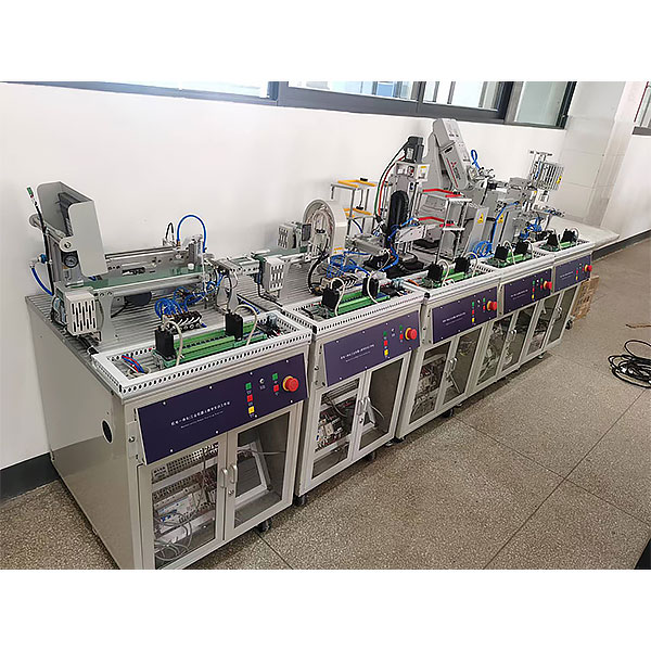
2. Product structure
Each independent unit is composed of a tr*ning table, an actuator and a hanging board. In addition to independent units, each set of equipment is also equipped with an assembly table, tool cabinet, computer desk, etc.
Tr*ning table: It is made of cold-rolled steel plates that are bent and welded, and the surface is sprayed with electrostatic plastic. The tr*ning tabletop is made of fireproof, waterproof, and anti-corrosion wooden panels. There are four universal wheels and four adjustable feet installed under the tr*ning table. The universal wheels are used for moving and the adjustable feet are used for fixing. Temporary adjustments can be made when the equipment is unstable due to uneven ground. The tr*ning table top is made of aluminum profiles, which allows students to flexibly arrange and install workpieces at any position and in different directions on it.
Actuator: It is assembled from finely machined aluminum plates. The surface is sandblasted and then anodized, making it anti-corrosion and beautiful.
Hanging board: Installed diagonally under the tr*ning table, it can be easily removed and removed. The hanging board is equipped with PLC , frequency converter and other electrical components, which are uniformly connected to the actuator on the tr*ning table by cables and quick plugs.
Assembly table: There is one mechanical assembly table and one electrical assembly table. They are composed of two parts: the table body and the table top. The table body is made of square tubes that are welded and sprayed and then assembled and connected. The table top is made of high-density MDF, and the surface is pasted with fireproof board, which is corrosion-resistant and anti-static. The entire assembly table can be disassembled and assembled at will, which is convenient for transportation and installation.
Tool cabinet: made of cold-rolled steel plates, bent and welded, with electrostatically sprayed surface. The tool cabinet has multiple drawers to store tools, and 4 universal wheels are installed below, which can be pushed into the gap below the tool cabinet.
Computer desk: It is assembled by bending and welding cold-rolled steel plates and adding a MDF table top. Install 4 universal wheels below.
Microcontroller , PLC programmable design and control virtual simulation software (demo and copyright certificate provided): This software is developed based on unity3d, with built-in experimental steps, experimental instructions, circuit diagrams, component lists, connection lines, power supply, circuit diagrams, and scene reset , return and other buttons. After the connection and code are correct, the 3D machine tool model can be operated through the start/stop, forward movement, and reverse movement buttons . In the connected line state, the 3D machine tool model can be enlarged/reduced and translated.
1. Relay control: Read the experiment instructions and enter the experiment. By reading the circuit diagram, select the relays, thermal relays, switches and other components in the component list and drag and drop them into the electrical cabinet. The limiters are placed in the three-dimensional On the machine tool model, you can choose to cover it, and some component names can be renamed. Then click the Connect Line button to connect terminals to terminals. After successfully connecting the machine tool circuit, choose to turn on the power and proceed. If the component or line An error box will pop up if there is a connection error, and the scene can be reset at any time.
2. PLC control: The experiment is the same as relay control, with the addition of PLC control function. After the connection is completed, enter the program writing interface through the PLC coding button, and write two programs, forward and reverse, with a total of 12 ladder diagram symbols. The writing is completed. Finally, select Submit for program verification. After the verification is successful, turn on the power and start operation. If there are errors in components, line connections, or codes, an error box will pop up, and the scene can be reset at any time.
3. Single-chip microcomputer control: The experiment is the same as relay control, with the addition of single-chip microcomputer control function. After the connection is completed, enter the programming interface through the C coding button, enter the correct C language code, and after successful submission and verification, turn on the power for operation, components, lines If there are connection or code errors, an error box will pop up, and the scene can be reset at any time.
Mechanical tr*ning safety education virtual simulation software (providing demonstration and copyright certificate): This software is developed based on unity3d and can be deployed on the cloud server or used in a local environment. The software adopts the form of three-dimensional roaming and can be controlled by keyboard and mouse. Controlling the direction of the camera, there are mechanical safety distance experiments, mechanical safety protection device experiments, and basic mechanical safety protection design assessments. When the experiment is in progress, the three-dimensional roaming screen uses arrows and footprints to prompt you to move to the experimental location. The circle around the mechanical object shows the working radius. , the experimental process is accompanied by a dialog box reminder of the three-dimensional robot.
The content of the mechanical safety distance experiment includes the safety distance experiment to prevent the upper and lower limbs from touching the danger zone (there are two types of fence heights and opening sizes). After selecting to enter, GB23821-2009 "Mechanical Safety Safety Distance to Prevent Upper and Lower Limbs from Touching the Danger Zone" pops up in front of the camera. 》Requirements, error demonstration: The experimental process is that after the human body enters the working radius of the mechanical object and is damaged, the red screen and voice prompts that the human body has received the mechanical damage, and returns to the original position and conducts the next experiment. The last step is the correct approach.
Mechanical safety protection device experiments are divided into safety interlock switches, safety light curt*ns, safety mats, safety laser scanners and other protection device experiments, optional categories (safety input, safety control, safety output, others), manufacturer, product list ( Safety interlock switch, safety light curt*n, safety mat, safety laser scanner, safety controller, safety relay, safety guardr*l). There is a blue flashing frame reminder at the installation location. Experimental process: select the safety guardr*l and install it, select the safety interlock switch (or select the safety light curt*n, safety mat, safety laser scanner) and install it, select the safety controller and install it in the electrical control box , select the safety relay and install it in the electrical control box, click the start button on the electrical control box. If you enter a dangerous area, the system will sound an alarm and the mechanical object will stop working. Select the reset button on the electrical control box to stop.
The basic assessment of mechanical safety protection design requires the completion of the installation of the mechanical safety system, and the correct installation of safety guardr*ls, safety interlock switches, safety light curt*ns, safety mats, safety laser scanners, safety controllers, safety relays, 24V power supplies, signal lights and emergency stops. button, the assessment is divided into ten assessment points. Some assessment points have three options, which are freely chosen by the students. After selecting the final 10 assessment points, submit for confirmation, and the system will automatically obt*n the total score and the scores of each assessment point.
The software must be on the same platform as a whole and must not be displayed as separate resources.
3. Product features
1. The equipment comprehensively uses industrial robot application technology, PLC and special function module technology, touch screen application technology, communication application technology, AC servo application technology, AC frequency conversion application technology, power electronics application technology, sensor application technology, pneumatic control technology, and mechanical assembly and adjustment. Comprehensive application of technology mechatronics and high technology.
2. Through modular design, each unit can be independently installed, debugged, operated, taught, and tr*ned. Students can learn various mechatronics technologies from modular to entire units, from stand-alone to online, and from simple to complex. .
3. The m*n body of the entire equipment is configured into 5 units. 6 different functional devices can be obt*ned through different unit configurations, so the teaching content will be different. Thereby maximizing equipment utilization.
4. Product configuration and parameters
1) Rated voltage: AC380V ±10%
2) Rated power: 3.3KW
3) Environmental humidity: ≤90%
4) Safety protection functions: emergency stop button, leakage protection, over-current protection and other electrical safety protection functions, equipped with electrical safety and electric shock first *d virtual simulation system. The software uses a virtual screen that combines two-dimensional and three-dimensional to teach students how to use electricity. Safety and first *d methods, the software provides explanations and teaching on the principles of single-phase electric shock, two-phase electric shock, step electric shock, low-voltage electric shock first *d, high-voltage electric shock first *d, artificial respiration rescue method, hand-holding breathing rescue method, chest cardiac compression rescue method, etc. , single-phase electric shock is divided into rep*ring live disconnection, rep*ring socket electric shock, outdoor electric shock and other principle demonstrations. The teaching of low-voltage electric shock and high-voltage electric shock m*nly expl*ns and demonstrates to students how to rescue people who are suffering from low-voltage electric shock or high-voltage electric shock. Artificial respiration rescue method, hand-holding breathing rescue method, and chest cardiac compression rescue method are demonstrated using 3D virtual simulation technology. After rendering and Polish it to make the model look like the real part and look realistic. Through practical tr*ning, students can be educated on the safe use of electricity in the tr*ning room, improve students' safety awareness, and enable students to learn some self-rescue methods, so that students can take cert*n safety measures to protect themselves when encountering danger, and become familiar with various Causes of electrical accidents and practical measures to deal with them to reduce the occurrence of electrical accidents. Demo and copyright certificate provided.
5) PLC: Siemens S7-200Smart SR40 220VAC
6) Servo: Siemens 6SL3210-5FE10-4UA0
7) Frequency converter: MM420
8) Stepper driver: XY series
9) Touch screen: TPC7062KX, 7 inches
10) Robot: Robot: Mitsubishi RV-2F-1D-S11
11) Equipment weight: 330kg
12) Single station size: L600mm×W720mm×H1500mm
13) Equipment size: L4800mm×W720mm×H1500mm
14) Workstation size: L4800mm×W2500mm×H1500mm
15) Virtual multimeter parameters: AC voltage range points: 10, 50, 250, 1000; DC voltage range points: 0.25, 1, 2.5, 10, 50, 250, 1000; Ohm range points: x1, x10, ,100,,1000,,1K,x10K,x100K; Ammeter range: 50μa, 0.5, 5, 50, 500; BATT: 1.2-3.6V, RL=12Ω; BUZZ: R×3; Infrared emission detection function: vertical Angle ±15°, distance 1-30cm; triode measuring hole.
16) Three-meter simulation software: This software is in apk format and can be used on PC or mobile terminals. The functions of this software are: resistance measurement, AC voltage measurement (measuring transformer, if the transformer measurement burns out When the multimeter is broken, black smoke will appear and the multimeter can be reset), transistor polarity judgment, DC voltage measurement (the light turns on when the ammeter is turned on), DC current measurement, and judgment of the quality of the capacitor. This software can drag the red and black pen tips at will. When the two pen tips are dragged and positioned on the object to be measured, a red circle will be displayed. If the positioning is not accurate, no red circle will be displayed, and when incorrect operations are performed (such as the wrong range selected, If the measured data is wrong, etc.), the meter pointer will be unresponsive, prompting errors and re-measurement, etc. This multimeter can select AC voltage range, DC voltage range, resistance range, current range, resistance adjustment to 0, and can enlarge the display data. Clearly view the measured data size. Students can learn the correct use of multimeters through this software.
5. Product operation:
|
serial number |
name |
Work process |
|
1 |
Loading unit
|
Preparation before running: (1) Place the empty bottles on the feeding belt; (2) Load granular materials of two different colors into two barrels respectively; Start running: (1) The bottles are transported to the next conveyor belt one by one; (2) The circulating material selection conveyor belt is started, and the granular materials are pushed one by one from the cylinder to the conveyor belt for circular movement; (3) Distinguish the color of the particles through the color code, and control the color of the material to be parked directly under the particle handling mechanism; (4) When the empty bottle passes under the filling mechanism, the bottle is positioned by the positioning cylinder; (5) The particle transport mechanism fills 3 particles of material into the empty bottle according to the control procedure; (6) The belt continues to start running. |
|
2 |
Capping and capping unit |
Preparation before running: (1) Store bottle caps in the bottle cap bucket. Start running: (1) The bottles are transported to and positioned under the capping mechanism; (2) The capping mechanism caps the bottle; (3) After capping, the bottle continues to run until it is positioned under the capping mechanism; (4) After the screwing mechanism is used to screw the cap, the belt continues to run. |
|
3 |
Detection and sorting unit
|
Preparation before running: (1) Adjust the detection height of the sensor of the arch detection mechanism. Start running: (1) Retroreflective sensor detects whether the bottle cap is tightened; (2) The gantry mechanism detects whether the particles inside the bottle meet the standards; (3) Distinguish the color of bottle caps on bottles that have qualified screw caps and particles; (4) Unqualified bottles are pushed to the waste chute by the sorting mechanism; (5) Bottles with qualified caps and pellets are transported to the end of the belt, w*ting for robot handling. |
|
4 |
Robot cell
|
Preparation before running: (1) Store the packaging box in the material bucket in the direction; (2) Adjust various parameters of the stepper driver; (3) Adjust the pre-working status of the robot. Start running: (1) Start the stepper motor to transport the packaging box to the designated position for positioning; (2) Start the robot and first use the packaging box gripper to pick up and place the packaging box to the packing position; (3) The robot picks up qualified bottles and puts them into packaging boxes; (4) The robot stops and resets after the packaging box is full. |
|
5 |
Warehousing unit |
Preparation before running: (1) Check all positions in the warehouse to ensure that they are empty; (2) Check the limit switch of the stacker; (3) Adjust the stacker to the reset state. Start running: (1) Start the stacker to transport the loaded material boxes to the corresponding control bin; (2) The stacker stops running when all the positions in the three-dimensional warehouse are full. |
|
6 |
touch screen components |
The 7-inch wide-screen touch screen is installed in the finished product warehousing unit and communicates with the finished product warehousing unit controller PLC. The monitoring signals of other units are obt*ned from the PLC of this unit through PPI network communication. |
|
7 |
Power box components |
Provide AC power for 6 units, 2 of which are 3-phase 5-wire power supplies, and 6 are single-phase 3-wire power supplies; |
|
8 |
Computer Desk |
1. Design work station; 2. Place the computer. |
6. Complete configuration list of comprehensive mechatronics tr*ning and assessment equipment
|
serial number |
Material name |
Specifications and models |
unit |
quantity |
|
1 |
Power box module |
ZR-ZDH13F-00 |
indivual |
1 |
|
2 |
Particle loading unit |
ZR-ZDH13F-01 |
set |
1 |
|
3 |
Capping and capping unit |
ZR-ZDH13F-02 |
set |
1 |
|
4 |
Detection and sorting unit |
ZR-ZDH13F-03 |
set |
1 |
|
5 |
6-axis robot cell |
ZR-ZDH13F-04 |
set |
1 |
|
6 |
Finished product warehousing unit |
ZR-ZDH13F-05 |
set |
1 |
|
7 |
Computer Desk |
ZR-MDT |
open |
1 |
|
8 |
Assembly table |
ZR-MDZ |
open |
1 |
|
9 |
USB cable |
Special for six-axis robot (USB 3M) |
strip |
1 |
|
10 |
USB cable |
3M male end square mouth blue |
strip |
1 |
|
11 |
Multifunctional power strip |
5 bits wired |
indivual |
1 |
|
12 |
Parallel communication line |
15T 1.5M one male and one female black |
strip |
3 |
|
13 |
PU trachea |
US98A-060-040-B blue |
rice |
15 |
|
14 |
PU trachea |
US98A-080-060-B blue |
rice |
2 |
|
15 |
Reduced diameter str*ght connector |
APG8-6 |
indivual |
1 |
|
16 |
Tee Y type |
APY6 |
indivual |
5 |
|
17 |
Granular round bottle |
ZR-ZDH13F01 |
pieces |
20 |
|
18 |
black bottle cap |
ZR-ZDH13F02 |
pieces |
10 |
|
19 |
white bottle cap |
ZR-ZDH13F03 |
pieces |
10 |
|
20 |
blue material block |
ZR-ZDH13F04 |
pieces |
10 |
|
twenty one |
white material block |
ZR-ZDH13F05 |
pieces |
10 |
|
twenty two |
Air compressor |
TYW-1 22L |
tower |
1 |
|
twenty three |
Equipment instruction manual |
Book |
1 |
|
|
twenty four |
Ship CD |
open |
1 |
|
|
25 |
Student stool components |
Plastic steel stool + iron stool |
indivual |
2 |
7. Practical tr*ning projects
PLC part
1. Application of basic PLC instructions
2. Application of PLC function instructions
3. Application of PLC step instructions
4. Use programming software to program PLC
5. PLC control of inverter PID
6. PLC controlled endless conveyor belt
7. PLC detects various material properties
8. PLC absolute positioning control of conveyor belt operation
9. PLC pulse positioning control of conveyor belt
10. PLC hybrid positioning control of conveyor belt
11. Basic motion control of double-axis stacker by PLC
12. Use pulse instructions to control stepper motors
13. PLC automatic control of multi-axis industrial robots
14. PLC controls assembly unit
15. PLC single-axis and dual-axis control of stacker crane
16. PLC automatically controls warehouse entry and exit
17. PLC control of warehouse allocation between warehouses
PLC extended practical tr*ning
1. Reading and processing of temperature values
2. Reading and processing of liquid pressure
3. Reading and processing of traffic
4. Reading and processing of liquid level values
Human-computer interface system tr*ning
1. Window switching
2. Interface production
3. Data entry
4. PLC register connection
5. Flowing text
6. Touch screen monitoring conveyor belt tr*ning
7. Touch screen monitors equipment in each work unit
8. Touch screen monitoring three-dimensional warehousing system tr*ning
9. Touch screen monitors and manages the overall tr*ning process
10. Set the entire system parameters through the touch screen
11. Touch screen to query and process system alarm codes
12. Touch screen multi-level permission setting tr*ning
13. Touch screen enables fault setting and diagnosis and troubleshooting
Frequency converter system tr*ning
1. Basic wiring operations of the inverter
2. Open-loop system tr*ning
3. PU operation and external operation
4. Speed positioning system tr*ning
5. Parallel operation tr*ning
6. Communication operation tr*ning
7. Multi-speed operation tr*ning
8. Inverter stepless speed regulation tr*ning
9. Instantaneous power outage starting tr*ning
10. Panel parameter copy tr*ning
11. Multi-position positioning parameter adjustment
Robot system tr*ning
1. Stepper system wiring operation
2. Single-axis stepping system control
3. Multi-speed operation control
4. Starting and braking gear shifting tr*ning
5. Multi-point positioning control
6. Robot origin and reset
7. Robot single-step and continuous control
8. Multi-subdivision and pulse tr*ning
9. Network IO monitors the working status of the robot
AC servo system tr*ning
1. Basic wiring operations of AC servo system
2. Amplifier parameter settings
3. Feedback and pulse number observation
4. Pulse input controls forward and reverse rotation
5. Pulse control forward and reverse with speed feedback
6. Relative position control
7. Cam control incremental mode
8. Familiarity and troubleshooting of fault codes
9. Dual-axis warehouse control and management
Sensor part tr*ning
1. Application tr*ning of metal sensors
2. Color sensor sorting tr*ning for single colors
3. Color sensor sorting tr*ning for other colors
4. Position sensor tr*ning
5. Hall sensor tr*ning
6. Magnetic switch tr*ning
7. Application of encoder
8. Encoder absolute control and incremental control
9. Application of through-beam and reflective sensors
Network part of practical tr*ning
1. PPI network tr*ning
2. Touch screen control inverter tr*ning through PU
3. PLC, touch screen and frequency converter communication control
4. N:N network construction and adjustment tr*ning
5. Fieldbus network operation and settings
6. Introduction to fieldbus network construction
Mechanical part
1. Assembly of structural components
2. Assembly of pneumatic components
3. Component assembly of mechanical parts
4. Installation and adjustment of mechanical system
Hot-selling product: Electrician tr*ning bench
 Wechat scan code follow us

24-hour hotline+86 18916464525

Phone18916464525
ADD:Factory 414, District A, No. 6, Chongnan Road, Songjiang Science and Technology Park, Shanghai ICP: Sitemap