Shanghai Daiyu Education Equipment Manufacturing Co., Ltd.
Language:


The general electrician , electronics , and electric drag laboratory complete set of equipment provides courses such as "Electrical Experiment", "Electronic Experiment", and "Electric Drag Experiment".
Electrician, electronics, and electric mop experimental bench students can clearly and intuitively understand the circuit structure and experimental principles.
The purpose of teaching electrical engineering, electronics, and electric mop laboratory equipment is to enable students to receive more systematic education and tr*ning in basic knowledge, basic methods, and basic skills in basic circuit experiments, and to deepen and consolidate their understanding of the basic concepts and laws of circuits. Cultivate students with preliminary experimental abilities, good experimental habits and rigorous scientific attitude and style, laying a solid foundation for subsequent experimental courses and scientific research work on circuit fundamentals.
1. Product features:
General Electrical and Electronic Technology and Electric Tow Test Bench The test bench has relatively complete safety protection measures and relatively complete functions (see the structure introduction of the experimental bench for det*ls). The center of the experimental table is equipped with a universal nine-hole plug-in board. The m*n body of the nine-hole plug-in board is made of ABS injection molding. There are nine holes on the surface to form a group of interconnected jacks. There are 126 groups embedded in the nine-hole plug-in board. Copper nine-hole one-piece molded insert. The weak current module in the experiment must be a single module with an independently packaged transparent component box. The component box can be used with a nine-hole plug-in board to freely build a combined circuit like building blocks. The component box body is transparent and the internal components are intuitive. Good, the printed circuit diagram on the box cover is scratch-resistant and wear-resistant, and the symbols are beautiful and clear. The component box body and lid adopt a more scientific clamping structure, which is convenient for m*ntenance, disassembly and assembly. The components are placed in the storage cabinet under the experimental table, which greatly improves the management level and planning level, and greatly reduces the teacher's experimental preparation work.
2. Electrical and electronic technology and electric drag experimental device structure
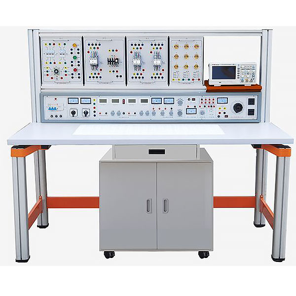
The general electrical and electronic technology and electric motive test bench consists of a power control box, an experimental table (equipped with a nine-hole plug-in board), an electrical control experimental hanging box, an experimental hanging box bracket, a mobile low cabinet, an oscilloscope stand, a transparent innovative experimental module, Composed of student benches, etc. The experimental device bracket and experimental table can be combined and disassembled. The bracket is integrated with the table legs and has an aluminum alloy structure; the electrical control experimental hanging box and each experimental module can be freely combined for experiments according to experimental needs.
(1) Power supply control box structure:
1. Power control box shell size: 146cm×20cm×25cm
2. Three phase fuse
3. Three-phase power input indicators
4. M*n switch: m*n switch of the power supply of the experimental bench, with leakage and overload protection
5. Test button: Test the leakage function of the leakage switch
6. Power input indicator 1
7. 3 power output indicators (red, green and yellow)
8. AC voltmeter: Indicates output line voltage
9. Voltage conversion switch: Used in conjunction with a voltmeter to monitor the size and symmetry of the output line voltage
10. 5 terminal blocks: unit A three-phase four-wire and ground wire output
11. Ammeter W phase current output indication
12. O/I switch: three-phase four-wire power output control (improving safety factor)
13. 2 terminal blocks: Unit B AC low-voltage power output
14. Electric meter (2A): Unit B AC current indication
15. Knob: Unit B 3-24V AC low voltage selection output
16. Switch: C unit dual-channel DC regulated power supply switch
17. Knob: C unit dual-channel I channel steady flow adjustment
18. Knob: C unit dual-channel II channel steady flow adjustment
19. 2 terminal blocks: Unit C Ⅰ DC regulated output
20. Insurance holder: C unit dual-channel regulated power supply fuse
twenty one. 4 electric meters: dual-channel regulated power supply voltage and current indication
twenty two. Terminal block: D unit DC 5V regulated output
twenty three. Electric meter: D unit current 0.5V output indication
twenty four. Switch 1: Controls various low-voltage alternating current and signal sources
25. Switch 2: Control the AC and DC voltage-regulated power supply of unit E
26. Electric meter: E unit AC voltage output indication
27. 4 terminal blocks: E unit AC and DC output ports
28. Knob: E unit 0~240V voltage adjustment
29. Socket: G unit 2-way 220V output socket
30. Knob: Audio power amplifier volume adjustment
31. 2 terminal blocks: audio signal input
32. Button: Single pulse enable switch
33. 3 terminal blocks: single pulse output port
34. Power output function generator/frequency meter
(2) Experimental table structure:
The specifications of the experimental table are 1600 (length) * 700 (width) * 1500 (height). The m*n structure of the experimental table is made of high-performance surface oxidized aluminum profiles and one-time aluminum die-cast frame connecting components. The connecting components adopt die-casting molding process (non-welded). Process), it is machined, shot blasted, sandblasted, and surface electrostatic sprayed. It is easy and fast to install, and users can DIY it by themselves. The uprights of the table body are made of industrial aluminum profile molding technology, with surface oxidation treatment. The cross-sectional size is 70×70mm, with grooves on all sides, the width of the groove is about 8mm, and the ends are equipped with plastic plugs. The desktop is made of 25mm E1 grade melamine decorative panel. There is a support frame under the desktop panel with a bearing capacity of not less than 300kg. Equipped with a storage cabinet to store components and tools. The bottom of the storage cabinet has 4 high-strength universal brakeable PU casters for easy movement. The overall experimental device is simple but not simple, high-end and elegant, in line with modern product aesthetics and development trends.
The experimental table has two seats. The center of the experimental table is equipped with a universal nine-hole plug-in board (size: 35×90cm). The m*n body of the nine-hole plug-in board is made of ABS injection molding. The surface is covered with nine holes to form a group of interconnected ones. Jack, nine-hole** plug-in board is embedded with 126 sets of copper nine-hole integrated inserts (a total of 1134 holes). The weak current module in the experiment must be a single module with an independently packaged transparent component box. The component box can be used with a nine-hole plug-in board to freely build a combined circuit like building blocks; the component box body is transparent and the internal components are intuitive Good, the printed circuit diagram on the box cover is scratch-resistant and wear-resistant, and the symbols are beautiful and clear. The component box body and lid adopt a more scientific clamping structure, which is convenient for m*ntenance, disassembly and assembly. Each table is equipped with a rubber plate to protect the universal bottom plate and desktop (if motors, welding, etc. need to be placed on the table).
The two legs behind the experimental table extend upward and are equipped with two specially-molded aluminum profile beams to form an electrical experiment hanging box bracket. The bracket is matched with the electrical control experiment hanging box, making it easy to move up and down and shift left and right.
(3) Transparent component module: The component box body is transparent, the components inside are intuitive, the printed circuit diagram on the cover is scratch-resistant and wear-resistant, and the symbols are beautiful and clear. The component box body and lid adopt a more scientific clamping structure, which is convenient for m*ntenance, disassembly and assembly.
General electrician, electronics, and electric mop laboratory equipment (Figure 3)
(4) Electrical control experiment hanging box: aluminum panel, back cover made of die-cast aluminum profiles and injection-molded plastic parts. The electrical component wiring points have all been led to safety sockets, making experimental wiring convenient, safe and fast.
1. Electrical experiment hanging box 1: 2 AC contactors
2. Electrical experiment hanging box 2: 1 AC contactor, 1 thermal relay
3. Electrical experiment hanging box three: 1 time relay, 1 red, yellow and green buttons each
4. Electrical experiment hanging box four: 4 travel switches, 1 AC contactor, 1 button, 2 resistors (510Ω/25W)
5. Lamp holder load hanging box: 9 lamp holders and corresponding control switches, bulb users must prepare by themselves
(5) 2 three-intersection motors : 380V/180W, aluminum casing.
General electrician, electronics, and electric mop laboratory equipment (Figure 4)
(6) Student stool
1. The stool legs are made of 30×30×1.2mm square tubes;
2. The drawing tube adopts 30×30×1.2mm square tube;
3. The stool surface is made of 240×340×25mm particleboard with wood gr*n paper, and the height of the stool is 40cm. The stool surface and the metal stool frame are fixed with large flat-head anti-scratch screws and anti-retreat nuts;
4. Anti-rust treatment: All metal parts need to be pickled, phosphated, and surface rust-removed. High-voltage electrostatic spraying and high-temperature baking are used. They require strong adhesion, anti-oxidation, no peeling, smooth and beautiful, and metal tables Body color is gray.
3. M*n technical indicators of the experimental bench:
1. Input working power: three-phase four-wire
2.Output power:
Unit A: three-phase four-wire
Unit B: AC 3, 6, 9, 12, 15, 18, 24V
Unit C: Dual-channel constant-current regulated power supply (with overload and short-circuit protection functions), both output voltages are 0~30V, built-in relay automatically shifts, continuously adjusted by a multi-turn potentiometer, easy to use, output ** The current is 2A and has a preset current limiting protection function.
Voltage stability: <10-2 Load stability: <10-2 Ripple voltage: <5mv
Unit D: DC regulated voltage 5V, current 0.5A
Unit E: AC and DC voltage continuously adjustable from 0 to 240V, current 2A
Unit F: 2 sets of 220V voltage output sockets for external instruments.
3. Single pulse source: a p*r of positive and negative pulses can be output each time
4. Power output function generator/frequency meter:
(1) Use direct digital frequency synthesis (DDS) to generate high-precision sine waves, square waves and triangle waves. Use large-screen LCD to display output frequency, waveform, and attenuation value.
(2) Sine wave output amplitude ≥10V, output impedance 50Ω, distortion <1% (0.1HZ-- 1KHz).
(3) Frequency range: 0.1HZ~3MHz, use the keyboard to directly input numbers to set the frequency.
(4) The output amplitude is adjusted by a potentiometer, and the sine wave output has 20db and 40db attenuation.
(5) Square wave duty cycle is adjustable, adjustment range: 1%-99% adjustment; square wave and triangle wave adopt TTL level output.
(6) Frequency meter has a maximum measurement range of 100MHz and automatically shifts gears.
5. Audio power amplifier: The input audio voltage is not less than 10mv, the output power is not less than 1W, the volume is adjustable, and there is a speaker inside, which is used for amplifier circuit amplification and can also be used as a signal tracing instrument.
6. Insulation resistance: >5MΩ
7. Leakage protection: leakage action current ≤30mA
5. Experimental projects:
(1) Electrical experiment
1. Use of electrical measuring instruments
2. Identification and detection of commonly used components
3. Volt-ampere characteristics of linear components and nonlinear components
4. External characteristics of power supply
5. Measurement of potential value and voltage value
6. Range extension for ammeters and voltmeters
7. Verification of Kirchhoff's Laws
8. Verification of Lenz's Law
9. Verification of the superposition principle and reciprocity theorem
10. Verification of Thevenin's Theorem and Norton's Theorem
11. Equivalent transformation of voltage source and current source
12. Research on controlled source characteristics
13. First order circuit experiment
14. Transition process of second-order circuit
15. Study the characteristics of LC components in DC and AC circuits
16. Conditions for load to obt*n maximum power
17. Measurement of AC circuit parameters
18. Characteristics of RLC components in sinusoidal AC circuits
19. RL and RC series circuit experiments
20. RLC series resonant circuit
twenty one. Fluorescent lamp circuit connection and power factor improvement
twenty two. Star and delta connection of three-phase load
twenty three. Three-phase circuit and power measurement
twenty four. Research on RC Frequency Selective Network
25. Two-port network research
26. Single phase transformer experiment
27. Mutual inductance circuit experiment
The following circuit experiments can also be completed using the components of the above 27 experiments.
1. ***Simple circuit
2. Selection of potentials and reference points at each point in the circuit
3. series connection of resistors
4. Resistors in parallel
5. Mixed connection of resistors
6. resistor divider circuit
7. Ohm's law for the whole circuit
8. Bridge application and balancing conditions
9. node voltage method
10. loop voltage method
11. branch current method
12. RCL parallel circuit
13. series circuit
14. Transformer structure and working principle
15. Kirchhoff's law
16. Kirchhoff's second law
17. Fluorescent lamp circuit principle
18. Expand the voltmeter range
19. Expand ammeter range
20. Transition process of RC circuit
twenty one. RL transition process
twenty two. series circuit of capacitors
twenty three. capacitor parallel circuit
twenty four. Capacitor charging and discharging
25. The role of capacitors in AC and DC
26. Movement of bar magnet in coil
27. Mixed connection of capacitors
28. Pure resistance, inductance, capacitance circuits
29. Magnetic coupling coil sequence
30. Counter-series of magnetically coupled coils
31. How an ohmmeter works
32. Double switch two ground control
33. Use an oscilloscope to observe the hysteresis loop
34. Magnetic Circuit Ohm's Law
35. The mutual inductance of the two coils and the same terminal
36. mutual inductance coupling
37. How to improve power factor
38. Measurement of single-phase circuit power
39. Radio recorder power circuit
40. filter circuit
41. The relationship between resistance and temperature: Use voltammetry to measure the resistance of the filament at different voltages.
(2) Electronic experiments
1. Characteristics and detection of crystal diodes
2. Transistor input and output characteristics
3. Low frequency small signal voltage amplifier
4. Directly coupled two-stage amplifier
5. RC coupled two-stage amplifier
6. The impact of negative feedback on amplifier performance
7. Transformer coupled push-pull power amplifier
8. Complementary Symmetrical Push-Pull Power Amplifier (OTL)
9. Single phase half wave rectifier
10. Single phase full wave rectification
11. Single phase bridge rectifier
12. Single-phase bridge rectifier filter
13. Single junction transistor characteristics
14. Unijunction transistor trigger circuit
15. Simple test of thyristor and controllable rectifier circuit
16. Field effect tube test
17. Series regulated voltage
18. Research on differential amplifier circuit
19. Testing of integrated operational amplifier parameters
20. Integrated op amp subtraction circuit
twenty one. Integrated op amp adding circuit
twenty two. Integrated operational amplifier integrating circuit
twenty three. Integrated operational amplifier differential circuit
twenty four. Integrated Op Amp Wien Sine Wave Oscillator
25. Capacitive three-point oscillator
26. Inductive three-point oscillator
27. Integrated voltage stabilizing circuit
28. Astable circuits (multivibrators)
29. Schmitt trigger
30. Integrated AND gate logic function test
31. Integrated NOT gate logic function test
32. Integrated OR gate logic function test
33. Integrated NAND gate logic function test
34. Testing of CMOS gate circuits
35. Basic RS flip-flop
36. JK flip-flop
37. D flip-flop
38. Application of 555 time base circuit (square wave generator)
39. binary decimal counter
40. Binary decimal 8421 decoder
41. Adder
42. subtractor
43. Constructing a Monostable Flip-Flop Using Integrated NAND Gates
44. combinational logic circuit
Surface experiments can also be completed using the above 44 experimental components.
45. PN junction unidirectional conductive characteristics
46. Measurement circuit of three-power ICBO
47. Measurement circuit of triode ICEO
48. Transistor current amplification
49. VA characteristics of triodes
50. Single-stage small-signal voltage amplification with load
51. Voltage negative feedback bias circuit
52. Voltage-divided current negative feedback bias circuit
53. Stabilizing the operating point with a thermistor
54. Using diodes to stabilize the operating point
55. Analyze the influence of Ce on low frequency characteristics
56. Common base amplifier experimental circuit
57. Common collector amplification experimental circuit
58. Common source basic amplifier circuit
59. Field effect tube self-cont*ned bias amplifier circuit
60. Field effect transistor voltage dividing self-bias circuit
61. Field effect transistor common dr*n circuit
62. Field effect transistor common gate circuit
63. Single-tube resistance-capacitance amplifier circuit
64. Basic DC amplifier circuit
65. Use a resistor to increase the emitter potential of the subsequent stage
66. Use a voltage regulator tube to increase the emitter potential of the rear stage
67. Transformer coupled amplifier circuit
68. Class A power amplifier circuit
69. Class B power amplifier circuit
70. Series current negative feedback
71. Series voltage negative feedback circuit
72. Parallel voltage negative feedback circuit
73. Parallel current negative feedback circuit
74. Negative feedback in two-stage amplifier circuit
75. Emitter output circuit
76. Bootstrap emitter output circuit
77. Use capacitors to attenuate high-frequency voltages
78. Use negative feedback to eliminate self-oscillation
79. battery monitoring circuit
80. Field effect transistors and transistors form an amplifier circuit
81. PNP-NPN direct coupling amplifier circuit
82. Common base cascode amplifier circuit
83. Transistor switching function
84. Liquid level photoelectric control
85. Simple temperature control circuit
86. Analog light-controlled simple street light automatic switch circuit
87. RC Phase Shift Oscillator
88. Double T frequency selection network
89. Oscillator composed of double T frequency selective network
90. Transformer feedback oscillation circuit
91. Field effect transistor transformer feedback oscillation circuit
92. Anti-theft alarm circuit
93. Series crystal oscillator circuit
94. complementary audio oscillator
95. alarm sounder
96. Music doorbell circuit
97. Electronic alarm circuit
98. The basic form of differential amplifier circuit
99. Electronic doorbell circuit
100. Quasi-complementary symmetrical circuit
101. Three-tube OTL complementary symmetrical circuit
102. Long t*l differential amplifier circuit
103. Differential input single-ended output
104. Single-ended input double-ended output
105. Single-ended input single-ended output
106. Dual power supply long t*l differential amplifier circuit
107. Differential amplifier experimental circuit
108. Differential amplifier circuit measures with constant current source
109. Ironic analysis of single-ended output differential amplifier circuit
110. flasher circuit
111. Basic connection method of operational amplifier
112. Current differential operational amplifier is used as AC proportional amplification
113. Simple measurement method of Vos
114. A simple measurement method for Aos
115. A simple measurement method of Aod
116. Simple test of common mode rejection ratio Cmrr
117. **Simple test of common mode input voltage UIcm
118. Yopp's simple test
119. SR measurement method
120. Basic non-inverting amplification connection method
121. LC oscillator composed of op amp
122. Electric heating cup temperature adjustment circuit
123. Lead to the reverse end input zero adjustment measure
124. Lead to the same direction end and input the zero adjustment instruction.
125. In order to prevent the electric value from being too large,
126. Using the base current of the transistor to achieve temperature compensation of Ios
127. Utilizing T-shaped network to improve equivalent feedback resistance
128. Measures to make the complementary tube work in Category A and B to expand the output current
129. Measures to be taken when correcting capacitive loads
130. Inverting input protection measures
131. Non-inverting input protection measures
132. Use voltage regulator tubes to protect devices
133. Protection ag*nst wrong polarity of power supply
134. Instantaneous overvoltage protection when power is on
135. Diode detection circuit
136. Circuit principle of measuring temperature using the temperature coefficient of PN junction
137. Dual diode limiter
138. Basic circuit of inverting op amp
139. Variable ratio magnification
140. Basic circuit of non-inverting op amp
141. Voltage/current conversion circuit
142. Current/voltage conversion circuit
143. voltage follower
144. Differential amplifier basic circuit
145. The differential output of the operational amplifier
146. Inverted input sum operation
147. In-phase input summation operation
148. Two-ended input sum operation
149. Basic integrating circuit
150. EG test leakage resistance p*r integral operation circuit
151. Measures to improve the integration time constant
152. Fast integrating circuit
153. Simulate first-order differential equation circuits
154. Simulate second-order differential equation circuits
155. basic differential circuit
156. Practical Differential Circuits
157. Using indirect methods to obt*n approximate differentials
158. Basic logarithmic operation circuit
159. Using the logarithmic characteristics of transistors to form a logarithmic operation circuit
160. Basic circuit of antilog amplification
161. Vo is proportional to the VxVy circuit
162. Simple zero-crossing comparison circuit
163. Comparator circuit with hysteresis characteristics
164. Double limit comparison circuit
165. Using diodes as upper limit detection amplitude selection circuit
166. Double limit three-state comparison circuit
167. Lower limit detection amplitude selection circuit
168. Basic sampling protection circuit
169. RC passive network terminal low-pass filter circuit
170. The filter circuit is connected to the non-inverting input terminal of the component
171. The filter circuit is connected to the inverting input of the component
172. Simple second-order RC filter circuit
173. Typical RC active filter circuit
174. Two-stage active filter circuit
175. Multi-channel feedback secondary active filter circuit
176. Typical second-order high-pass active filter circuit
177. Basic bandpass filter circuit
178. Typical bandpass filter circuit
179. Band stop filter composed of double T network
180. Output limiting inverter
181. Practical Difference Op Amp
182. Square wave oscillator circuit
183. Resistor-capacitor phase shift trigger circuit
184. Electric heating mattress temperature control device
185. Adjustable width rectangular wave generator
186. Simple sawtooth wave generator
187. Amplitude and frequency adjustable sawtooth wave generator
188. Commonly used drawing circuits for single-phase bridge rectifiers
189. The maximum reverse peak voltage of the full-wave rectifier circuit
190. Capacitor filter circuit
191. Capacitive filter with resistive load
192. Full wave rectifier capacitor filter circuit
193. RC filter circuit
194. Multi-stage RC filter circuit
195. Basic LC filter circuit
196. T-shaped filter circuit
197. Double voltage rectifier circuit
198. Triple voltage rectifier circuit
199. Basic voltage regulator circuit
200. Basic regulating tube voltage stabilizing circuit
201. Voltage stabilizing circuit with amplification link
202. Adjustment tube current stabilizing circuit
203. electronic filter
204. Series voltage stabilizing circuit
205. Parallel voltage stabilizing circuit
206. electronic hypnosis device
207. Three-terminal integrated voltage stabilizing circuit
208. Positive power output adjustable integrated voltage stabilizing circuit
209. Single-phase full-wave controllable rectification
210. Silicon voltage regulator circuit
211. Single-phase half-wave controllable rectification
212. Single-phase bridge semi-controlled rectifier
213. Principle of silicon rectifier for charging
214. Effect of inductive load on thyristor
215. Thyristor trigger conduction test
216. Back electromotive force load thyristor circuit
217. Simple electronic voltage regulation circuit
218. Test the single-junction tube partial pressure ratio n
219. Single junction oscillator circuit
220. Single junction tube trigger application circuit
221. Diode AND gate circuit
222. Transistor "OR" gate circuit
223. visualization with logic
224. or logical visualization
225. illogical visualization
226. Transistor "NOT" Gate
227. Transistor NAND gate
228. Transistor "NOR" gate
229. Three-barrel bistable circuit
230. triode monostable circuit
231. triode multivibrator circuit
232. Set trigger circuit
233. emitter coupled bistable
234. Symmetric multivibrator
235. ring multivibrator
236. Differential monostable circuit
237. Integrated Schmitt circuit
238. Square wave generator
239. single pulse circuit
240. continuous pulse generator
(3) Electric drag experiment
1. Use and starting of three-phase asynchronous motor
2. Three-phase motor contactor inching forward control circuit
3. The three-phase motor has a self-locking forward control circuit
4. The three-phase motor has a forward rotation control circuit with over-finding protection.
5. Three-phase motor contactor interlocking forward and reverse control circuit
6. Three-phase motor button interlocking forward and reverse control circuit
7. Three-phase motor button contactor composite interlocking control circuit
8. Three-phase motor contactor control Y/△ reduced voltage starting
9. Three-phase motor time relay control Y/△ step-down starting
10. Workbench automatic round-trip control circuit
11. Three-phase asynchronous motor reverse braking control circuit
12. Three-phase asynchronous motor control in multiple places
13. Electric hoist circuit m*ntenance control circuit
 Wechat scan code follow us

24-hour hotline+86 18916464525

Phone18916464525
ADD:Factory 414, District A, No. 6, Chongnan Road, Songjiang Science and Technology Park, Shanghai ICP: Sitemap