DY Intelligent Manufacturing Digital Twin Virtual Simulation Experiment Platform
Release time:2024-07-06 23:30viewed:times
1. Software Introduction
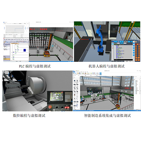
This software is a 3D intelligent manufacturing virtual simulation software. Based on a large number of element models , it can quickly build simulation projects by dragging and dropping. Virtual devices have the same characteristics as real devices. They are driven by actual PLC programs, robot programs, machine tool CNC programs, etc., and the debugging and verification of the entire project are completed in the virtual scene. Through the mechanical physics engine, the actual operation effect is achieved.
The software integrates functions such as PLC simulation, robot simulation, and intelligent factory simulation. It provides users with autonomous modeling and autonomous layout functions, and opens the underlying interface to support user secondary development. It is a comprehensive design simulation verification platform for industrial 4.0 automation, and provides rich teaching resources. In
the industrial field, the entire system can be fully analyzed in the primary concept stage of production line design, including virtual debugging, beat verification, risk assessment, solution improvement, and reduction of project technical risks. In the education field, through object virtualization, the problem of high engineering tr*ning costs and few scenarios is solved. It can be used for college student competitions, open experiments, graduation projects, etc.
Recommended hardware system configuration
In order to ensure smooth use of the system, the configuration requirements of the computer system are:
Operating system: Windows 7 SP1 and above
System type: 64-bit operating system
Processor (CPU): ≥2.5Ghz (if using VR glasses, ≥3.2Ghz)
Memory: ≥8GB
Hard disk: ≥5GB
Video memory: ≥1GB (using VR glasses, video memory ≥6GB, such as GTX1070)
.Net framework version: V4.6.2 and above
Software features
1. Virtual integration of Industrial 4.0 system
Including self-developed models, automatic layout, electrical connection design, programming, virtual debugging, and the entire system integration process.
2. Virtual and real combination simulation of multi-brand PLC
Supports semi-physical simulation (virtual and real combination) and full virtual simulation of various m*nstream brand PLCs.
3. Virtual and real combination simulation of multi-brand robots
Supports semi-physical simulation (virtual and real combination) and full virtual simulation of various m*nstream brand industrial robots.
4. Intelligent manufacturing virtual and real simulation
In addition to PLC and industrial robots, it has expanded the elements required for intelligent manufacturing such as CNC machine tools, machine vision, AGV, RFID, etc.
5. MES system access
The virtual intelligent factory has an MES data acquisition interface, which can seamlessly access the industrial-grade MES system to build a virtual intelligent factory.
6. Intelligent factory digital twin
The virtual production line developed in 1:1 exchanges data with the on-site production line in real time and runs synchronously to form a digital twin system.
7. Rich teaching resources
A series of teaching resources for PLC, robots, and intelligent manufacturing have been developed, which saves time and effort for teachers to teach.
2. M*n functions of the software
1. Autonomous layout
For three-dimensional graphics, no programming is required, and users can quickly build projects by dragging and dropping. The model can be moved, rotated, edited, assembled, etc., and the model after layout is completed can be driven by various peripherals.
2. Physical engine
The built-in physical engine creates a three-dimensional model with physical properties that can simulate physical phenomena in real life, such as motion, rotation, and elastic collision. In the motion simulation of collision, friction, and force, different physical properties can obt*n different motion effects.
3. Human-computer interaction
The operation of virtual devices is driven by the control device through the program. The virtual sensor can feedback the state of the scene, giving the virtual device the same characteristics as the actual device. The virtual device can also be operated through the external real control panel or the control panel on the virtual device.
4. Three-dimensional operation of the scene
The operation of translation, rotation, zooming, etc. can be completed through the keyboard and mouse, and the perspective can be quickly switched. It has a three-view function, supports top view, front view, and left view, and can view the three-dimensional scene from multiple perspectives at the same time.
2. M*n functions of the software
1. Autonomous layout
Facing three-dimensional graphics, no programming is required, and users can quickly build projects by dragging and dropping. The model can be moved, rotated, edited, assembled, etc., and the model after layout is completed can be driven by various peripherals.
2. Physical engine
The built-in physical engine creates a three-dimensional model with physical properties, which can simulate physical phenomena in real life, such as: movement, rotation, and elastic collision. In the simulation of collision, friction, and force, different physical properties can obt*n different motion effects.
3. Human-computer interaction
The operation of virtual devices is driven by the control device through the program. The virtual sensor can feedback the state of the scene, giving the virtual device the same characteristics as the actual device. The virtual device can also be operated through the external real control panel or the control panel on the virtual device.
4. Scene 3D operation
The keyboard and mouse can complete operations such as translation, rotation, and zooming, and the perspective can be quickly switched. It has a three-view function, supports top view, front view, and left view, and can view the 3D scene from multiple perspectives at the same time.
5. Simulation scene operation wizard
It has a device introduction function. Clicking on the device can display det*led information of the device, and the device information can be edited. It has an operation guidance function to guide the user to complete the operation step by step. Each step of the operation has corresponding prompts, and the operation steps can be edited.
6. VR glasses experience
Achieve immersive virtual reality 3D experience, including realistic industrial scene 3D sound simulation, so that the experiencer is immersed in the scene. The handle can be used to interact with the scene.
7. Multiple authorization modes
Support network authorization mode and dongle authorization mode.
8. Online update
The software detects whether there is a new version from the cloud and prompts the corresponding operation. 3D models support cloud updates. The software can view cloud models and use them in simulation scenes.
9. Massive models
Cont*ns a complete and typical model library of industrial equipment, which can be directly dragged and used in simulation scenes, and the parameters of the model can be set. Cont*ns m*nstream brand industrial robots, conveyors, pneumatic parts, motors , push buttons, sensors, visual cameras, CNC machine tools, stereo warehouses, AGVs, robot fixtures, etc.
10. Model development
Import 3D parts from external CAD files, give them parameters and motion characteristics in the software, and generate virtual devices developed by users themselves. Virtual devices can be driven by external controllers, such as PLCs, robot teaching pendants, etc. Import 3D file formats supported: STEP, STP, OBJ, FBX, STL, etc.
11. Peripheral port mapping
The virtual device of the simulation scene exchanges data with the external controller through a variety of communication protocols, supporting bus communication protocols such as Modbus-RTU, Modbus-TCP, OPC UA, S7, etc. Through the device data mapping table, the external controller port is mapped to the internal port of the 3D model, so the external controller can drive the virtual device to work, and the user can modify the data mapping table by himself.
12. Electrical system integration
For the design of electrical signal connection diagrams, the electrical m*n control device and the controlled device of the simulation scene have a corresponding electrical symbol, which is represented by a graphic with a name and an internal port number. Connect different ports by drawing lines, and different types of ports are represented by lines of different colors. After completing the electrical signal connection diagram, the IO table in Excel format can be exported.
13. Automatic evaluation
The software has the functions of real-time data collection and analysis and automatic scoring. First, the teacher will ask questions on the software and automatically generate scoring rules. During the assessment process, the software will record the student's operation process, execution results, and abnormal events in real time, and calculate the final score according to the examination scoring rules, which will reduce the teacher's workload and improve the teaching quality.
15. Hardware PLC simulation
The software supports hardware PLCs of m*nstream brands such as Mitsubishi and Siemens , communicates with the hardware PLC bus, reads PLC signals in real time, and drives the virtual devices of the simulation scene in real time.
16. Virtual PLC simulation
The software supports virtual PLC simulators of m*nstream brands such as Mitsubishi and Siemens. The virtual PLC drives the virtual devices of the simulation scene in real time. The PLC programming development software can download PLC programs and monitor the program operation of the virtual PLC in real time.
17. Configuration software debugging
The simulated human-machine interface developed by the configuration software can control the virtual PLC and operate the virtual devices of the simulation scene.
18. Trajectory design based on CAD data The
robot motion trajectory can be based on CAD data to simplify the trajectory generation process and improve the accuracy. The motion trajectory can be directly generated using the workpiece model. Supports general CAD files: stp, step, etc.
19. Robot offline programming
Supports offline programming operations for industrial robots of ABB, KUKA, Funac, Yaskawa, and m*nstream brands at home and abroad. The workpiece 3D model can be imported and trajectory planning can be performed. The optimized spatial forward and inverse solution algorithm is used to simulate the motion process, and the complex programming process can be completed with one click. Through the post-code function, the robot code of each brand can be directly generated to simplify the programming process of industrial robots.
20. Collision detection
It can detect the collision between two parts of the robot. When the collision occurs, the colors of the two parts automatically turn red. At the same time, the collision log is recorded. The log includes the name, location, and time of the collision device.
21. Trajectory optimization
Provides a variety of trajectory optimization tools during offline programming: the collision detection tool checks whether there has been a collision during simulation operation to prevent danger in real application; the trajectory analysis tool checks the accessibility, posture singularity, axis overlimit, and beat estimation of the industrial robot, which is convenient for designers to adjust the robot trajectory and avoid unexpl*ned shutdown during actual operation; the robot 3D working range ball can intuitively display the maximum and minimum working range of the robot to improve debugging efficiency.
22. Rich process toolkits
Provides a variety of process toolkits: customize tool models and coordinate parameters according to needs to meet personalized workstation design requirements. The coordinate transformation between the virtual design environment and the real application environment is realized through the multi-point intelligent matching algorithm, and all landmarks are transformed without changing the trajectory profile to improve adaptability. It integrates typical process applications such as robot palletizing, robot loading and unloading, and robot welding.
23. Robot dragging teaching
Supports dragging the robot flange end or tool end for translation and rotation operations to obt*n spatial points. The spatial points can be turned on or off, and the points can be moved.
24. Virtual teach pendant programming
Built-in robot virtual teach pendant, the function and interface are consistent with the real teach pendant. The virtual teach pendant program drives the robot movement and IO operation, and completes robot programming, motion simulation, robot process tr*ning and other functions.
25. Hardware teach pendant programming
The real teach pendant is connected to the software through the Ethernet bus, and the robot programming and control of the virtual robot movement are completed on the hardware teach pendant, completing various robot virtual and real combination simulations. While ensuring operational safety, it does not affect the operating experience.
26. Simultaneous simulation of multiple robots
Supports multiple types of robots, such as right-angle robots, SCARA robots, 4-axis serial robots, and 6-axis serial robots. Each robot has an independent motion controller, which is programmed and runs independently. Supports simultaneous simulation of multiple brands and types of robots.
27. Machine vision simulation
The virtual camera in the simulation scene can exchange data with the external machine vision software in real time to form a machine vision system to achieve online visual inspection of virtual workpieces. The machine vision software communicates with the virtual robot bus, transmits the workpiece coordinates to the virtual robot, and guides the virtual robot to grab the workpiece.
28. AGV simulation
The virtual AGV car has the same characteristics as the physical AGV car, and supports AGV tracking, station docking and other operations.
29. RFID simulation
It has a virtual RFID reader and a virtual RFID tag. The RFID reader can read and write RFID tags. PLC can read the virtual RFID reader information.
30. CNC cutting simulation
Supports CNC machine tool cutting simulation, including turning and milling. The workpiece performs dynamic cutting according to the actual G code, supplemented by chips, coolant and other effects. With the virtual probe, it supports virtual online measurement.
31. MES system access
The MES system is the core component of the intelligent manufacturing production system, and interacts with the production line system in real time. The virtual production line has the same interface as the physical production line. The operating status of the robots, PLCs, machine tools, workstations, stereoscopic warehouses and other equipment in the virtual production line can be collected in real time by the MES system, and receive MES production instructions to build a complete industrial 4.0 intelligent manufacturing development simulation environment.
32. Digital twin function
Virtual equipment developed according to the actual equipment characteristics, the production line is arranged in 1:1, the virtual production line and the actual production line are set up through port mapping to interact with the data in real time, and keep running synchronously, forming a digital twin function. Performance analysis and optimization can be completed in the virtual production line.
33. Support cloud experiments
Online experiments can be completed with the supporting teaching resource website. The steps include but are not limited to: courseware learning, video learning, online simulation experiments, project download, project opening, start exam, complete automatic exam evaluation, and upload exam results.
34. Integrated course resources
Course resources developed based on the software platform, including knowledge points, courseware, micro-class videos, three-dimensional scenes, reference programs, automatic assessment papers, etc., are imported into the software platform through standard formats to form a new form of interactive integrated teaching materials. Compared with traditional teaching materials, learning efficiency is improved through knowledge points, micro-class videos, three-dimensional scene interactive operations, etc.
35. Simulation experiment resources
Provide 21 PLC basic experiment simulation projects, 4 industrial robot workstation simulation projects, and 10 intelligent manufacturing production line simulation experiments.
36. Electricity safety and electric shock first *d virtual simulation system The
software uses a combination of two-dimensional and three-dimensional virtual images to teach students electricity safety and first *d methods. The software is equipped with single-phase electric shock, two-phase electric shock, step electric shock, low-voltage electric shock first *d, high-voltage electric shock first *d, artificial respiration rescue method, hand-holding breathing rescue method, chest external cardiac compression rescue method and other principle explanations and teaching, single-phase electric shock is divided into m*ntenance of live disconnection, m*ntenance of socket electric shock, outdoor electric shock and other principle demonstrations. The teaching of low-voltage electric shock and high-voltage electric shock m*nly expl*ns and demonstrates to students how to rescue people who are in low-voltage electric shock or high-voltage electric shock. Artificial respiration rescue method, hand-holding breathing rescue method, and chest compression rescue method are displayed using 3D virtual simulation technology. After rendering and polishing, the model looks the same as the real parts, and the picture is realistic. Through practical tr*ning, students can be educated on safe use of electricity in the tr*ning room, improve their safety awareness, learn some self-rescue methods, and take cert*n safety measures to protect themselves when they encounter danger, and be familiar with the causes of various electrical accidents and practical operational measures to deal with electrical accidents, so as to reduce the occurrence of electrical accidents.
37. Mechanical assembly and bench assembly virtual simulation software
Based on unity3d design, users can choose different interactive interface sizes according to computer configuration, and can choose six levels of image quality. 4 types of cylindrical gear shaft system components, 4 types of bevel gear shaft system components, and 6 types of worm shaft system components can be selected for installation, disassembly, assembly, component measurement (divided into shaft measurement and base measurement), assessment, etc. There are intelligent reminders during the steps of disassembling and assembling parts. Students manually select the corresponding parts and move them to the shaft structure. Only when the parts are selected in the correct order can they be installed. The models in the software are all 3D models, made by 3Dmax, and rendered and polished to make the models look the same as real parts. There are non-standard parts library (8 parts), standard parts library (12 parts), and measuring tool library (steel ruler, vernier caliper) for disassembly and assembly selection. The software is equipped with electronic experimental assessment questions and instructions that integrate the purpose, steps, requirements, etc. of the experiment. When using the assessment function, questions are asked for students to answer. When students finish answering the questions, the assessment score is given. There are 12 questions in total, and each question is set to 8 points (one of which is a multiple-choice question, accounting for 12 points). Only when the answer is selected can the next question be asked. The software must be able to rotate, zoom in, and zoom out to view its det*ls in all directions. The software must be on the same platform as a whole and must not be displayed as a separate resource.
38. Virtual simulation software for mechanical tr*ning safety education: This software is developed based on Unity3D and can be deployed on the cloud server or used in the local environment. The software adopts the form of 3D roaming, and the movement can be controlled by the keyboard and the direction of the camera can be controlled by the mouse. It has mechanical safety distance experiments, mechanical safety protection device experiments, and basic assessments of mechanical safety protection design. During the experiment, the 3D roaming screen uses arrows and footprints to prompt movement to the experimental position. The circle around the mechanical object shows the working radius. The experimental process is accompanied by a dialog box reminder of the 3D robot.
A. The content of the mechanical safety distance experiment includes the safety distance experiment to prevent the upper and lower limbs from touching the dangerous area (divided into 2 types of fence heights and opening sizes). After choosing to enter, the GB23821-2009 "Safety Distance for Mechanical Safety to Prevent Upper and Lower Limbs from Touching Dangerous Areas" requirements pop up in front of the camera. Wrong demonstration: The experimental process is that after the human body enters the working radius of the mechanical object and is injured, the bloody screen and voice reminders are received. Mechanical injury, and then return to the original position and conduct the next experiment. The final step is the correct approach.
B. Mechanical safety protection device experiments are divided into safety interlock switches, safety light curt*ns, safety mats, safety laser scanners and other protection device experiments. Optional categories (safety input, safety control, safety output, others), manufacturers, product lists (safety interlock switches, safety light curt*ns, safety mats, safety laser scanners, safety controllers, safety relays, safety fences). The installation location has a blue flashing frame reminder. The experimental process is: select the safety fence and install it, select the safety interlock switch (or select the safety light curt*n, safety mat, safety laser scanner) and install it, select the safety controller and install it to the electrical control box, select the safety relay and install it to the electrical control box, and click the start button on the electrical control box. If you enter the dangerous area, the system will prompt an alarm sound, and the mechanical object will stop working. Select the reset button on the electrical control box to stop.
C. The basic assessment of mechanical safety protection design requires the installation of the mechanical safety system to be completed, and the safety guardr*l, safety interlock switch, safety light curt*n, safety mat, safety laser scanner, safety controller, safety relay, 24V power supply, signal light and emergency stop button to be correctly installed. The assessment is divided into ten assessment points, and some assessment points have three options, which are freely selected by students. After the final 10 assessment points are selected, submit for confirmation, and the system automatically calculates the total score and the score of each assessment point.
D. The software must be on the same platform as a whole and must not be displayed as a separate resource.


 Wechat scan code follow us
