DY semi-physical PLC virtual simulation teaching experiment platform
Release time:2024-07-06 22:00viewed:times
System Introduction
The software supports users to quickly create their own 3D industrial scenes by dragging and dropping, and can control 3D industrial scenes in real time through internal virtual PLC or external real PLC. It acts as a real-time automation sandbox to realize product simulation, analysis and optimization process before actual product manufacturing. The system includes functions such as industrial 3D scene construction, PLC programming, and PLC control system debugging. It has high teaching value in industrial automation, mechatronics , electrical engineering, mechanical
engineering, and other courses. In the primary concept stage of automation product design, the entire system can be fully analyzed, and the mutual movement of each component can be observed and experimented. In the virtual scene, design defects can be easily modified, different layout schemes can be simulated, and the automation product system can be continuously improved until the optimal design scheme is obt*ned.
It provides users with autonomous modeling and autonomous layout functions, and opens the underlying interface to support user secondary development. It is a comprehensive design simulation verification platform for industrial 4.0 automation, and provides rich teaching resources.
Hardware requirements:
In order to ensure smooth use of the system, the configuration requirements for the computer system are listed here:
Operating system: Windows 7 SP1 and above
System type: 64-bit operating system
Processor (CPU): ≥2.5Ghz (if using VR glasses, ≥3.2Ghz)
Memory: ≥8GB
Hard disk: ≥5GB (storage space)
Graphics card: GPU ≥800MHz Video memory ≥1GB (if using VR glasses, GPU ≥1.6Ghz, video memory ≥6GB, such as GTX1070)
Net framework version: V4.6.2 and above
I. Software Features
1. Virtual system integration
Users can independently develop models , automatic layout, electrical signal connection, virtual debugging, and verify the entire process of system integration.
2. Multi-brand PLC virtual and real combination simulation
Supports semi-physical simulation (virtual and real combination) and full virtual simulation of PLCs of various m*nstream brands.
3. The automatic assessment function
collects the action data of the PLC scene in real time, and the system automatically calculates the assessment results according to the assessment requirements.
4. Rich teaching resources
Based on the PLC experiment outline, the teaching resources are developed based on software, independently released and downloaded from the Internet. A series of PLC teaching resources suitable for secondary vocational schools, higher vocational schools and undergraduate schools are constantly enriched.
5. Module expansion (need to be equipped separately)
The software is based on modular design and can be expanded to robot simulation and intelligent manufacturing simulation.
II. M*n functions of the software
(1) Basic simulation function
1) Automatic layout
In a 3D scene, users can quickly change the construction project by dragging and dropping. The model can be moved, rotated, edited, assembled, etc., and the work scene deployment is completed like building blocks. After the layout is completed, the scene can be driven by various peripherals.
2) Physical effect
The system has a built-in physics engine. The virtual model created has physical effects and can simulate physical phenomena in real life, such as gravity, elastic collision, etc. In the motion simulation of collision, friction and force, different dynamic properties can obt*n different motion effects.
3) Human-computer interaction
The movement of virtual devices is driven by programming, and virtual sensors can feedback the real state of the scene, giving virtual devices the same characteristics as actual devices. The scene can be operated through the control panel on the virtual device, the panel on the HMI, and the external hardware panel. It is like operating a real scene.
4) VR experience
The software supports VR glasses to achieve an immersive virtual reality 3D experience. It includes realistic industrial scene 3D sound simulation, which makes the experiencer feel like they are in the scene. The scene can be interactively operated through the handle.
5) Peripheral bus driver
Supports data exchange with external systems through the bus. For example, connect to a bus-type external hardware controller to form a virtual-real combination simulation system. Or perform secondary development applications through the bus. Supports Modbus-RTU bus devices (such as various serial port sensors and actuators), Modbus-TCP bus devices (such as various network port sensors and actuators), and OPC bus devices (such as OPC servers and WinCC software).
6) Electrical connection and system integration
The software supports the integration of various virtual devices and virtual debugging in virtual scenes. Virtual integration is m*nly operated through port mapping: associate the controllable part of the model with a specific port number, and operate the virtual device by operating this port number. Such as various robot tools, assembly lines, sensors, etc. The ports include: level ports, analog ports, and pulse ports. Through the signal operation of the port, the system integration of the robot is completed, and a complex robot application system is built.
7) Virtual-real combination technology
To control the operation of virtual devices, it can be a software controller or an external hardware controller. Therefore, a full-software virtual simulation or a semi-physical virtual-real combination simulation can be established to enrich the scope of application.
8) Massive models
The system cont*ns a complete component library with typical industrial equipment, and provides corresponding motion simulation and effect rendering for the components in the library. The corresponding components can be selected for design according to engineering requirements. Such as various conveyor belts, pneumatic cylinders, hydraulic cylinders, servo motors , screws, profiles, buttons, switches, sensors , CNCMachine tools, machining centers, stereoscopic warehouses, AGV and other industrial elements.
9) Model development
The system opens a general interface for CAD data import, builds model components for non-standard machines that are not in the component library, and assigns them parameters and movements. The system has a powerful model reading function and can read 3D modeling in igs, step, stp, OBJ, and STL formats.
10) Development environment ecology
Model Network is a model sharing and communication website. Users can share designed models, technical discussions, and model transactions to improve the enthusiasm for creation and build an open ecological environment.
11) Automatic evaluation
The software has the function of operating data collection and analysis. Based on the software-based automatic evaluation system, the teacher first sets questions and automatically generates scoring rules. During the assessment process, the system will record the student's operation process, execution results, and abnormal events in real time, and calculate the assessment score according to the examination scoring rules. Reduce the workload of teachers' corrections and improve the quality of teaching. It can be used for after-class tests, experimental previews, course assessments, and vocational technical level examinations.
12) Script secondary development
Support Python scripting language programming to control virtual devices, which can be used for rapid function verification.
(2) Multi-brand PLC virtual-real combination simulation
The software integrates various actuators and sensors, such as: conveyor belts, pneumatic devices, motors, push button switches, sensors, CNC machine tools, stereoscopic warehouses, robot fixtures, customized actuators, etc. These devices can be driven by PLC, so this software is a very good PLC tr*ning software.
The software supports built-in virtual Mitsubishi PLC, virtual Siemens PLC, bus access hardware Siemens PLC, bus access hardware Mitsubishi PLC.
3. Teaching resources
The teaching resources are based on software development, independent release, and network download. Based on the PLC experimental outline, a series of PLC intelligent manufacturing teaching resources suitable for secondary vocational schools, higher vocational schools, and undergraduate schools have been developed and continuously enriched.
Virtual simulation teaching system
Mechanical tr*ning safety education virtual simulation software: This software is developed based on unity3d. The software adopts the form of 3D roaming. The movement can be controlled by the keyboard and the direction of the camera can be controlled by the mouse. There are mechanical safety distance experiments, mechanical safety protection device experiments, and basic assessments of mechanical safety protection design. During the experiment, the 3D roaming screen uses arrows and footprints to prompt movement to the experimental position. The circle around the mechanical object shows the working radius. The experimental process is accompanied by a dialog box reminder of the 3D robot.
A. The content of the mechanical safety distance experiment includes the safety distance experiment to prevent the upper and lower limbs from touching the dangerous area (divided into 2 types of fence heights and opening sizes). After choosing to enter, the GB23821-2009 "Mechanical safety to prevent the upper and lower limbs from touching the dangerous area" requirements pop up in front of the camera. Wrong demonstration: The experimental process is that after the human body enters the working radius of the mechanical object and is injured, the bloody screen and voice reminder receive mechanical injury, and return to the original position and conduct the next experiment. The last step is the correct approach.
B. Mechanical safety protection device experiments are divided into safety interlock switches, safety light curt*ns, safety mats, safety laser scanners and other protection device experiments. Optional categories (safety input, safety control, safety output, others), manufacturers, product lists (safety interlock switches, safety light curt*ns, safety mats, safety laser scanners, safety controllers, safety relays, safety fences). The installation location has a blue flashing frame reminder. The experimental process is: select the safety fence and install it, select the safety interlock switch (or select the safety light curt*n, safety mat, safety laser scanner) and install it, select the safety controller and install it to the electrical control box, select the safety relay and install it to the electrical control box, and click the start button on the electrical control box. If you enter the dangerous area, the system will prompt an alarm sound, and the mechanical object will stop working. Select the reset button on the electrical control box to stop.
C. The basic assessment of mechanical safety protection design requires the completion of the installation of the mechanical safety system, the correct installation of safety guardr*ls, safety interlock switches, safety light curt*ns, safety mats, safety laser scanners, safety controllers, safety relays, 24V power supplies, signal lights and emergency stop buttons. The assessment is divided into ten assessment points, some of which have three options, which are freely selected by students. After the final 10 assessment points are selected, submit for confirmation, and the system automatically obt*ns the total score and the score of each assessment point.
D. The software must be on the same platform as a whole and must not be presented as a separate resource.
E. At the same time, the VR installation package of this software is provided to customers to facilitate users to expand it into VR experiments. VR equipment and software installation and debugging do not need to be provided.
Mechanical assembly and bench assembly virtual simulation software: This software is developed based on unity3d, with optional 6 levels of image quality, and has the design and virtual disassembly and assembly of reducers and shaft systems, design and simulation of common mechanical mechanisms, mechanism resource library, typical mechanical mechanisms (virtual disassembly and assembly of gasoline engines). The software is an overall software and cannot be a separate resource.
A. Reducer design and virtual disassembly and assembly interface can choose worm gear bevel gear reducer, two-stage expanded cylindrical gear reducer, bevel cylindrical gear reducer, coaxial cylindrical gear reducer, bevel gear reducer, and one-stage cylindrical gear reducer.
Worm bevel gear reducer: After entering the software, the assembly content will be automatically played, and each step in the video will be described in text.
Secondary unfolded cylindrical gear reducer: After entering the software, the content will be played in the form of video. The video content should include: part name (scan the QR code to see the part name), disassembly demonstration (including disassembly, assembly), virtual disassembly (including the whole, low-speed shaft, medium-speed shaft, high-speed shaft, box cover, box seat)
Bevel cylindrical gear reducer, coaxial cylindrical gear reducer, bevel gear reducer, first-level cylindrical gear reducer: click to enter and automatically jump to the edrawings interface. The models are all three-dimensional models. By clicking on the parts to display the part name, you can rotate 360° in all directions, zoom in, zoom out, and translate. At the same time, you can use the move parts function to disassemble and assemble the entire reducer. At the same time, you can select the home button to return to the original state of the reducer. The bevel gear reducer and the first-level cylindrical gear reducer have added the function of inserting cross sections, and the cross sections can be freely dragged to observe the internal structure of the reducer.
B. The design of the shaft system structure and the virtual disassembly and assembly interface can select part recognition, disassembly and assembly demonstration, and actual combat operation.
1. Part recognition: The three-dimensional models and part names of helical gears, end caps without holes, couplings, coupling keys, shafts, gear keys, end caps with holes, sleeves, and deep groove ball bearings are built in. Any part can be rotated 360°
2. Disassembly and assembly demonstration: There are 2 built-in cases. When the mouse is moved to a cert*n part position (except the base and the bearing seat), the part is automatically enlarged and the part name is displayed. There are disassembly and assembly buttons. The software automatically completes the disassembly and assembly of the shaft system structure. The three-dimensional scene can be rotated, enlarged, reduced, and translated 360° in all directions.
3. Actual operation: The three-dimensional parts are neatly placed on the desktop. Students manually select the corresponding parts and move them to the shaft system structure. The parts can only be installed when the placement order and position are correct. There is a restart button to facilitate students to re-perform virtual experiments. When the mouse is moved to a cert*n part position (except the base and the bearing seat), the part is automatically enlarged and the part name is displayed.
C. Common mechanical mechanism design and simulation optional hinge four-bar mechanism design and analysis, I\II type crank rocker mechanism design and analysis, offset crank slider mechanism design and analysis, crank swing guide rod mechanism design and analysis, hinge four-bar mechanism trajectory synthesis, eccentric linear roller push rod cam , and concentric linear flat bottom push rod cam .
1. Each mechanism should be able to input corresponding parameters, and the software will automatically calculate the parameters, and can perform motion simulation and automatically draw curves.
D. The mechanism resource library can choose 11 types of planar connecting rod mechanisms, 5 types of cam mechanisms, 6 types of gear mechanisms, 8 types of transmission mechanisms, 11 types of tightening mechanisms, 6 types of gear tr*n mechanisms, and 8 types of other mechanisms (mechanical equipment simulation).
E. Virtual disassembly and assembly of gasoline engines can choose crankcase assembly and disassembly demonstration, crankcase virtual assembly, valve tr*n assembly and disassembly demonstration, and valve tr*n virtual assembly.
1. The crankcase assembly and disassembly demonstration and the valve tr*n assembly and disassembly demonstration are equipped with disassembly buttons, assembly buttons, restart buttons, and decomposition observation buttons. When the mouse moves to a cert*n part position, the part is automatically enlarged and the part name is displayed. The function is automatically completed by the software to disassemble and assemble the shaft system structure. When the decomposition observation button is used, the crankcase or valve tr*n 3D model automatically displays an exploded view, which can be rotated 360°, zoomed in, zoomed out, and translated.
2. The 3D parts of the crankcase virtual assembly and the valve tr*n virtual assembly are neatly placed on the desktop. Students manually select the corresponding parts and move them to the mechanism. The parts can only be installed when the placement order and position are correct. There is a restart button to facilitate students to repeat the virtual experiment. When the mouse moves to cert*n parts, the part name is automatically displayed.
(1) PLC Basic Experiment Simulation Resource Package (standard configuration)
The PLC Basic Experiment Simulation Resource Package is written based on the "Programmable Controller Programming Application" tutorial experiment. All experiments can be purely virtual simulations, and also support virtual combined with PLC simulation (semi-physical simulation). Each resource includes: tr*ning materials, videos, and engineering cases.
Experimental projects:
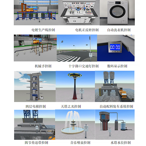
1. Motor sequential start control
2. Motor star-delta start control
3. Digital display control
4. Music fount*n control 5.
Assembly line control
6. Crossroad traffic light control
7. Water tower water level control
8. Sky Tower light control
9. Automatic batching and loading system control
10. Four-section conveyor belt control
11. Multiple liquid mixing device control
12. Automatic rolling mill control
13. M*l sorting machine control
14. Robot control
15. Four-story elevator control
16. Automatic washing machine control
17. Electroplating production line control
18. DC motor control
19. Temperature PID control
20. Analog variable frequency open-loop speed control
21. Analog variable frequency closed-loop speed control
(2) PLC Industrial Innovation Extended Simulation Resource Package
PLC Industrial Innovation Simulation Resource is based on commonly used industrial automation equipment, and the model is developed at a 1:1 ratio. Let students master typical industrial applications in school and lay a good foundation for future employment. All simulations support PLC virtual simulation and semi-physical simulation. Each resource includes: tr*ning materials, videos, and project cases.
Experimental projects:
1. Transmission line blocking control
2. Assembly line parallel control
3. Servo control
4. Right-angle robot assembly control
5. Gantry robot palletizing
6. Stereoscopic warehouse
7. Stereoscopic garage
8. Truss mechanical mobile bed loading and unloading
9. Liquid level control
(3) PLC integrated development extended simulation resource package
PLC integrated development simulation resource package, taking a typical automated vertical warehouse as an example, starting from product requirements, the control system requirements analysis, control system solution design, control system hardware design, equipment selection, equipment layout installation, equipment electrical connection, control system software design, PLC program development and debugging, human-machine interface development, system integration operation, function and performance verification. Complete the overall integrated development process of industrial automation products, and is based on virtual simulation software development and debugging. The equipment is a virtual device using simulation software, the equipment layout installation uses the layout function of simulation software, and the equipment electrical connection uses the electrical connection function of the software. PLC simulation programming and debugging uses the virtual PLC development and debugging function of simulation software. Resources include: tr*ning materials, videos, and project cases.
Experimental content:
1. Industrial project development process experiment
2. Industrial control design selection experiment
3.PLC scene layout experiment
4.Data mapping setting experiment
5.Electrical diagram layout experiment
6.HMI development and debugging experiment
7.Library program programming and debugging experiment
(4)PLC comprehensive application extended simulation resource packagePLC
comprehensive application resource package is a system that organically integrates robot technology, visual inspection technology, assembly line technology, hydraulic technology, PLC control technology, Internet of Things communication technology and system engineering. The system consists of 11 unit workstations, including pallet automatic stacking and unpacking unit, feeding unit, electromechanical processing simulation unit, capping unit, pinning unit, robot handling unit, robot handling unit, spray drying unit, inspection unit, logistics storage unit, and master control unit. It completes the entire process from blank to finished product assembly and warehousing.
Considering the high cost, large area, high knowledge density, high risk, and difficult teaching of physical production lines, all experiments in this project are completed in a simulation environment. Each student has an independent development environment. In the simulation software, they build their own smart factory from scratch, from production line planning, selection, layout, design, unit workstation virtual debugging, and complete system smart factory system joint debugging. All PLC programs, robot programs, and visual programs are virtually debugged and verified in the simulation software, and can be directly downloaded to the physical production line for operation. Resources include: tr*ning materials, videos, and engineering cases. Experimental projects:
1. Pallet automatic stacking and unstacking unit control experiment
2. Feeding unit control experiment
3. Electromechanical processing simulation unit experiment
4. Capping unit control experiment
5. Robot handling control experiment
6. Pinning unit control experiment
7. Telescopic reversing unit control experiment
8. Spraying and drying unit control experiment
9. Inspection unit control experiment
10. Robot sorting unit control experiment
11. Logistics unit control experiment
12. PLC networking experiment
13. System overall operation debugging experiment


 Wechat scan code follow us
