Shanghai Daiyu Education Equipment Manufacturing Co., Ltd.
Language:


| Resource Category | System Title | title | brief introduction |
|
education resources |
Elevator operation Principle introduction |
Elevator operation display |
Demonstrate how the elevator operates in the shaft. From the common appearance of the elevator to the internal structure, the coordinated operation of the various systems inside the elevator is demonstrated from multiple angles and perspectives; the four major spaces of the elevator are introduced, so that learners can have a holistic understanding of the elevator structure. |
| Elevator structure display | Show the decomposition of the entire elevator structure, introduce the various components of the elevator and their relative positions | ||
| Introduction to the eight major systems of elevators | The eight major systems of the elevator are disassembled and restored from the entire elevator to display and introduce the composition of each system. | ||
| Traction system | Traction principle demonstration | Demonstrate how the traction wire rope realizes the operation of the car through the traction sheave, and the principle of relative operation of the car and counterweight | |
| Traction system composition | Demonstrate the composition of the traction system | ||
| Three-dimensional display of geared traction machine | Display of the appearance of the geared traction machine | ||
| Display of gear traction machine structure | Introducing the structural composition of the geared traction machine through decomposition and display | ||
| Permanent magnet synchronous traction machine three-dimensional display | Display the appearance of permanent magnet synchronous traction machine | ||
| Permanent magnet synchronous traction machine composition display | Introduce the structure of the permanent magnet synchronous traction machine through decomposition and display | ||
| Brake structure display | Introduce the structure of the brake through decomposition display | ||
| Braking principle display | Demonstrate the braking principle of the brake | ||
| Traction wire rope display | Show the location of the traction wire rope and introduce the two common wire rope specifications for elevators | ||
| Rope head combination structure display | Introduce the structural composition of the rope head combination through decomposition and display | ||
| Guidance system | Guidance system components | The components of the display guidance system | |
| Car (counterweight) guide r*l display | Display the appearance and cross-sectional shape of the car (counterweight) guide r*ls, and the tongue-and-groove connection of the guide r*l connection position | ||
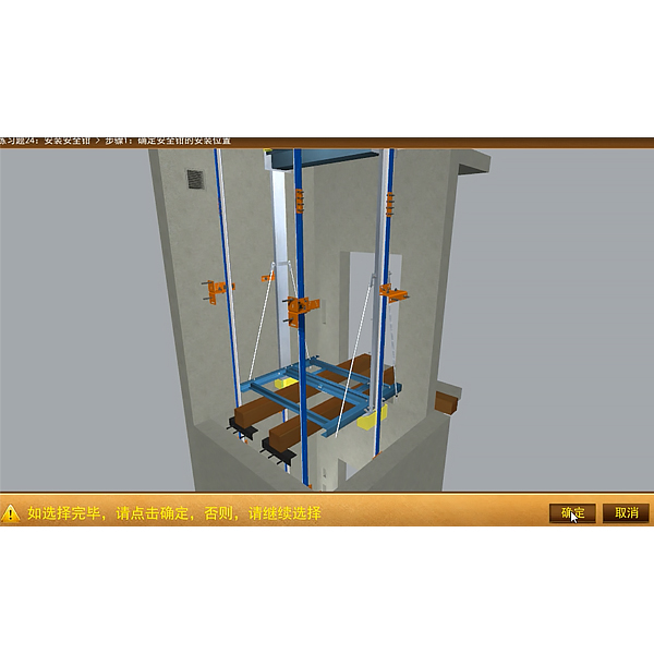
| Guide r*l bracket installation demonstration | Demonstrate the installation process of the guide r*l bracket | ||
| Guide shoe structure display | Display the installation positions of car guide shoes and counterweight guide shoes, the appearance of several commonly used guide shoes (one-way spring sliding guide shoes, rolling guide shoes, fixed guide shoes), and structural display | ||
| Car system | Car frame structure display | Demonstrate the structure of the car frame and introduce other components installed on the car frame | |
| Car structure display | Show the structure of the car and introduce other components installed on the car | ||
| Door systems | Door system components | Display door system components | |
| Double door knife car door three-dimensional display | Display the appearance of double door knife car door | ||
| Double door knife car door composition display | Through decomposition and display, the structural composition of the double-door knife car door is introduced | ||
| Double door knife car door opening and closing process display | Demonstrate the opening/closing process of the double-door knife car door | ||
| Single door knife car door three-dimensional display | Display the appearance of single door knife car door | ||
| Single door knife car door composition display | Through decomposition and display, the structural composition of the single-door knife car door is introduced | ||
| Single door knife car door opening and closing process display | Demonstrate the opening/closing process of the single-door knife car door | ||
| Floor door three-dimensional display | Display door appearance | ||
| Floor door composition display | Introduce the structural composition of the floor door through decomposition display | ||
| Door opening and closing display | Display the opening/closing process of the landing door | ||
| Linkage display of floor door and car door | Demonstrate the linkage opening/closing process of the landing door and car door, focusing on the coordination between the car door knife and the landing door roller | ||
| Weight balance system | Counterweight structure display | Show the appearance of the counterweight and introduce the structural composition of the counterweight by disassembling it | |
| Compensation ch*n structure display | Show the installation position, structural material and anti-drop protection of the compensation ch*n | ||
| Safety protection system | Introduction of elevator safety protection device | Through the demonstration, introduce the various safety protection functions of the elevator, the installation location, name and role of the safety protection device | |
| Overspeed protection: | |||
| Three-dimensional display of one-way safety gear | Display of the appearance of 3 types of one-way safety clamps (ball-type instantaneous safety clamp, wedge-type progressive safety clamp (disc spring, U-shaped leaf spring)) | ||
| One-way safety clamp structure display | Through decomposition and display, the structural composition of the commonly used U-shaped leaf spring wedge type progressive safety clamp (one-way) is introduced | ||
| Demonstration of the action principle of one-way safety clamp | Demonstrating the process of the one-way safety clamp pull rod lifting the wedge and then clamping it to the guide r*l | ||
| Bidirectional safety clamp 3D display | Display the appearance of the two-way safety clamp | ||
| Bidirectional safety clamp structure display | Introducing the structure of the commonly used U-shaped leaf spring wedge type progressive safety clamp (bidirectional) | ||
| Demonstration of the action principle of bidirectional safety clamp | Demonstrate the process of the bidirectional safety clamp pulling the wedge block under the action of the operating mechanism, and then clamping it upward (or downward) on the guide r*l, and at the same time demonstrate the process of the protection switch action | ||
| One-way speed limiter three-dimensional display | Display the appearance of a one-way speed limiter | ||
| One-way speed limiter structure display | By decomposing, the structural composition of the one-way speed limiter is shown | ||
| One-way speed limiter operation principle demonstration | Demonstrate how the one-way speed limiter locks the tongue when the car is overspeeding and descending, how the brake arm clamps the speed limiter wire rope, and how the lever toggles the switch | ||
| Bidirectional speed limiter three-dimensional display | Show the appearance of a two-way speed limiter | ||
| Bidirectional speed limiter structure display | By decomposing, the structural composition of the bidirectional speed limiter is demonstrated | ||
| The action principle of the two-way speed limiter | Demonstrate the process of how the two-way speed limiter engages the ratchet when locking the tongue, how the brake arm clamps the speed limiter wire rope, and how the lever toggles the switch when the car and the counterweight are overspeeding and descending | ||
| Speed limiter-safety gear linkage principle demonstration | Through four partial shots, it demonstrates step by step how the speed limiter - the safety clamp is linked when overspeeding occurs, and finally how the safety clamp wedge clamps the guide r*l | ||
| 3D display of speed limiter rope tensioning device | Display the appearance of the speed limiter rope tensioning device | ||
| Speed limiter rope tensioning device structure display | By disassembling, the structural composition of the speed limiter rope tensioner is demonstrated | ||
| Speed limiter rope breaking action demonstration | Demonstrate the process of simulating the breaking of the speed limiter rope, triggering the switch, and stopping the elevator | ||
| Rope Clamp 3D Display | Demonstrate the relationship between the rope clamp and the speed limiter, the appearance and structural composition of the rope clamp | ||
| Rope clamp action principle demonstration | Demonstrates the process of braking when the speed limiter brake arm brakes when the counterweight is overspeeding and the brake wire triggers the rope clamp to clamp the traction wire rope and implement braking | ||
| Pier bottom (top) protection: | |||
| Buffer 3D Display | Display the appearance of the hydraulic buffer | ||
| Buffer structure display | By disassembling, the structural components of the hydraulic buffer device are demonstrated | ||
| Buffer principle demonstration | Demonstrates the changes in the internal hydraulic oil and the switching process when the hydraulic buffer is pressed down | ||
| Near door safety protection: | |||
| Door anti-pinch device | Demonstrate the installation position, mechanism composition and protection action process of the safety touch panel anti-pinch device | ||
| Overrun protection: | |||
| Limit switch protection device |
Displays the installation location of the shaft overtravel protection switch, its functions, and the associated boards Animation shows the state of the elevator car when the boards touch the switches during the elevator's upward movement |
||
| Car door and floor door switch protection: | |||
| Door electrical interlock |
Display of the installation position of the car door (floor door) lock contact Display of the structure of the car door lock Display of the linkage between the floor door contact and the lock arm |
| Teaching Projects | Teaching tasks | Content introduction (knowledge and skills points) | Display form |
| Elevator space display | Four major spaces of elevator | Display the four major spaces of the elevator, including the machine room, shaft, landing station, pit, car, and car top | VR Interaction |
| Introduction to the m*n components of elevators | Three-dimensional display of geared traction machine | The gear traction machine has a full range of appearance and multi-angle display; | VR Interaction |
| Display of gear traction machine structure | Introduce the structure of the gear traction machine - traction wheel, reduction box, brake, traction motor , etc. | VR Interaction | |
| Brake structure display | Introduce the installation position and function of the brake, and the components of the vertical brake - brake wheel, brake arm, brake shoe, electromagnet, etc. | VR Interaction | |
| Brake operation principle demonstration |
Demonstrate the working principle of the brake; manual release and brake operation process. |
Animation | |
| Rope head combination structure display |
Introduce the installation position of the rope end assembly; Introduce the structure of the rope end assembly; |
VR Interaction | |
| Car (counterweight) guide r*l position display |
Introduce the function of the guide r*l; the size parameters of the T-shaped guide r*l; the difference between the car guide r*l and the counterweight guide r*l; the connection of the two guide r*ls; |
Animation | |
| Guide r*l bracket installation demonstration |
Introduce the installation method of the guide r*l; introduce the car guide r*l bracket and the counterweight guide r*l bracket; introduce the installation process of the bracket. |
Animation | |
| Guide shoe structure display |
Introduce the function of guide shoes; introduce several commonly used guide shoes and their uses; one-way spring sliding guide shoes; rolling guide shoes; fixed guide shoes. |
VR Interaction | |
| Car frame structure display |
Introduce the function of the car frame; introduce the structure of the car frame; introduce the m*n components installed on the car frame. |
VR Interaction | |
| Car structure display |
Introduce the function of the car; introduce the composition of the car; introduce other components installed on the car. |
VR Interaction | |
| Double door knife car door three-dimensional display | Display the appearance structure of the double door knife car door | VR Interaction | |
| Double door knife car door composition display | Decomposition and display of the structure of the double-door knife car door | VR Interaction | |
| Double door knife car door opening and closing process display | Demonstrate the opening and closing process of the double-door car door | Animation | |
| Single door knife car door three-dimensional display | Display the appearance structure of single door knife car door | VR Interaction | |
| Single door knife car door composition display | Decomposition and display of the structure of a single-door knife car door | VR Interaction | |
| Single door knife car door opening and closing process display | Demonstrate the opening and closing process of the single-door knife car door | Animation | |
| Floor door three-dimensional display | Display the appearance structure of the floor door | VR Interaction | |
| Floor door composition display | Decomposition and display of the structural components of the floor door | VR Interaction | |
| Display of the door opening and closing process | Demonstrate the opening and closing process of the landing door | Animation | |
| Linkage display of floor door and car door | Demonstrate the linkage opening and closing process of the landing door and car door from multiple directions and angles - the door motor drives the car door, the car door knife inserts into the landing door roller, and drives the landing door to open and close together. | Animation | |
| Double folding side door structure display | Analyze and show the structure of the bi-fold side-opening door | VR Interaction | |
| Double folding side door opening and closing action demonstration | Demonstrate the opening and closing action of the bi-fold side door | Animation | |
| Center bi-fold door structure display | Decomposition and display of the structural components of the center bi-fold door | VR Interaction | |
| Center-split bi-fold door opening and closing action demonstration | Demonstrate the opening and closing action of the center-split bi-fold door | Animation | |
| Counterweight structure display |
Introduce the installation position and function of the counterweight; introduce the structure of the counterweight; |
VR Interaction | |
| Compensation ch*n structure display |
Introduce the installation position and function of the compensation ch*n; introduce the structure of the compensation ch*n; |
Animation | |
| One-way safety gear three-dimensional display | Display the appearance and structure of 3 types of one-way safety clamps - ball type and wedge type | VR Interaction | |
| One-way safety clamp structure display | Decomposition and display of the structural components of the wedge-type progressive safety clamp | VR Interaction | |
| Demonstration of the action principle of one-way safety clamp | Demonstrate the clamping action process of the wedge-type progressive safety clamp | Animation | |
| Bidirectional safety clamp 3D display | Display the appearance and structure of the wedge-type two-way safety clamp | VR Interaction | |
| Bidirectional safety clamp structure display | Decomposition and display of the structural components of the wedge-type bidirectional safety clamp | VR Interaction | |
| Demonstration of the action principle of bidirectional safety clamp | Display the action process of the bidirectional clamping of the wedge-type bidirectional safety clamp from multiple angles | Animation | |
| Bidirectional speed limiter (with rope clamp) 3D display | Display the appearance of a two-way speed limiter (with rope clamp) | VR Interaction | |
| Bidirectional speed limiter (with rope clamp) structure display | Decomposition and display of the structure of the two-way speed limiter (with rope clamp) | VR Interaction | |
| Demonstration of the operating principle of the two-way speed limiter (with rope clamp) | Demonstrate the overspeed clamping action process of the two-way speed limiter (with rope clamp) | Animation | |
| Bidirectional speed limiter three-dimensional display | Display the appearance and structure of the bidirectional speed limiter | VR Interaction | |
| Bidirectional speed limiter structure display | Decomposition and display of the structure of the bidirectional speed limiter | VR Interaction | |
| The action principle of the two-way speed limiter | Demonstrate the overspeed clamping action process of the bidirectional speed limiter | Animation | |
| Speed limiter safety gear linkage principle demonstration | Demonstrating the operation of the speed limiter - safety clamp under normal and overspeed conditions. Four close-up shots of key locations | Animation | |
| 3D display of speed limiter rope tensioning device | Display the appearance and structure of the speed limiter rope tensioning device | VR Interaction | |
| Speed limiter rope tensioning device structure display | Disassembled display of the structure of the speed limiter rope tensioning device | VR Interaction | |
| Speed limiter rope breaking action demonstration | Demonstrate the action process of the speed limiter rope tensioner when the rope is broken (loose) | Animation | |
| Rope Clamp 3D Display | Display the appearance and structure of the rope clamp | VR Interaction | |
| Rope clamp action principle demonstration | Demonstrating the action process of the rope clamp clamping the traction wire rope in cooperation with the speed limiter | Animation | |
| Hydraulic buffer 3D display | Display of the appearance and structure of the hydraulic buffer and mounting bracket | VR Interaction | |
| Hydraulic buffer structure display | Disassemble and display the structure of hydraulic buffer | VR Interaction | |
| Hydraulic buffer action principle demonstration | Demonstrating the hydraulic buffer stroke compression action process | Animation | |
| Door anti-pinch device |
Introduce the installation location and function of the door-near protection device; introduce one of the anti-pinch device structures (structural decomposition); demonstrate the working principle of the anti-pinch device protection. |
Animation | |
| Elevator operation experience | Elevator Operation | Experience the normal operation of the elevator in a virtual scene | VR Interaction |
 Wechat scan code follow us

24-hour hotline+86 18916464525

Phone18916464525
ADD:Factory 414, District A, No. 6, Chongnan Road, Songjiang Science and Technology Park, Shanghai ICP: Sitemap