Shanghai Daiyu Education Equipment Manufacturing Co., Ltd.
Language:


The system uses computer simulation technology and 3D simulation technology, taking AC03 urban r*l electric passenger car as the prototype, to virtually construct the 3D structure, working principle, disassembly and assembly of the m*n systems and components including the overall appearance and internal layout of the vehicle , bogies, doors, couplers, pantographs, etc. All equipment and components should be consistent with the reference prototype equipment to meet the teaching and tr*ning functions of the vehicle and the m*n system structures.
Virtual simulation teaching system
Virtual simulation software for mechanical tr*ning safety education: This software is developed based on unity3d. The software adopts the form of 3D roaming. The movement can be controlled by the keyboard and the direction of the camera can be controlled by the mouse. There are mechanical safety distance experiments, mechanical safety protection device experiments, and basic assessments of mechanical safety protection design. During the experiment, the 3D roaming screen uses arrows and footprints to prompt movement to the experimental position. The circle around the mechanical object shows the working radius. The experimental process is accompanied by a dialog box reminder of the 3D robot.
A. The content of the mechanical safety distance experiment includes the safety distance experiment to prevent the upper and lower limbs from touching the dangerous area (divided into 2 types of fence heights and opening sizes). After choosing to enter, the GB23821-2009 "Safety Distance for Mechanical Safety to Prevent Upper and Lower Limbs from Touching Dangerous Areas" requirements pop up in front of the camera. Wrong demonstration: The experimental process is that after the human body enters the working radius of the mechanical object and is injured, the bloody screen and voice reminders are received. Mechanical injury, and then return to the original position and conduct the next experiment. The last step is the correct approach.
B. Mechanical safety protection device experiments are divided into safety interlock switches, safety light curt*ns, safety mats, safety laser scanners and other protection device experiments. Optional categories (safety input, safety control, safety output, other), manufacturers, product lists (safety interlock switches, safety light curt*ns, safety mats, safety laser scanners, safety controllers, safety relays, safety fences). The installation location has a blue flashing frame reminder. The experimental process is: select the safety fence and install it, select the safety interlock switch (or select the safety light curt*n, safety mat, safety laser scanner) and install it, select the safety controller and install it to the electrical control box, select the safety relay and install it to the electrical control box, and click the start button on the electrical control box. If you enter the dangerous area, the system will prompt an alarm sound, and the mechanical object will stop working. Select the reset button on the electrical control box to stop.
C. The basic assessment of mechanical safety protection design requires the completion of the installation of the mechanical safety system, the correct installation of safety guardr*ls, safety interlock switches, safety light curt*ns, safety mats, safety laser scanners, safety controllers, safety relays, 24V power supplies, signal lights and emergency stop buttons. The assessment is divided into ten assessment points, some of which have three options, which are freely selected by students. After the final 10 assessment points are selected, submit for confirmation, and the system automatically obt*ns the total score and the score of each assessment point.
D. The software must be on the same platform as a whole and must not be presented as a separate resource.
E. At the same time, the VR installation package of this software is provided to customers to facilitate users to expand it into VR experiments. VR equipment and software installation and debugging do not need to be provided.
Mechanical assembly and bench assembly virtual simulation software: This software is developed based on unity3d, with 6 levels of image quality optional, and has the design and virtual disassembly and assembly of reducers and shaft systems, design and simulation of common mechanical mechanisms , mechanism resource library, and typical mechanical mechanisms (virtual disassembly and assembly of gasoline engines). The software is an overall software and cannot be a separate resource.
A. Reducer design and virtual disassembly and assembly interface can choose worm bevel gear reducer, two-stage expanded cylindrical gear reducer, bevel cylindrical gear reducer, coaxial cylindrical gear reducer, bevel gear reducer, and one-stage cylindrical gear reducer.
Worm bevel gear reducer: After entering the software, the assembly content will be automatically played, and each step in the video will be described in text.
Secondary unfolded cylindrical gear reducer: After entering the software, the content will be played in the form of video. The video content should include: part name (scan the QR code to see the part name), disassembly demonstration (including disassembly, assembly), virtual disassembly (including the whole, low-speed shaft, medium-speed shaft, high-speed shaft, box cover, box seat)
Bevel cylindrical gear reducer, coaxial cylindrical gear reducer, bevel gear reducer, first-level cylindrical gear reducer: click to enter and automatically jump to the edrawings interface. The models are all three-dimensional models . By clicking on the parts to display the part name, you can rotate 360° in all directions, zoom in, zoom out, and translate. At the same time, you can use the move parts function to disassemble and assemble the entire reducer. At the same time, you can select the home button to return to the original state of the reducer. The bevel gear reducer and the first-level cylindrical gear reducer have added the function of inserting cross sections, and the cross sections can be freely dragged to observe the internal structure of the reducer.
B. The design of the shaft system structure and the virtual disassembly and assembly interface can select part recognition, disassembly and assembly demonstration, and actual combat operation.
1. Part recognition: The built-in 3D models and part names of helical gears, end caps without holes, couplings, coupling keys, shafts, gear keys, end caps with holes, sleeves, and deep groove ball bearings are set. Any part can be rotated 360°.
2. Disassembly and assembly demonstration: There are 2 built-in cases. When the mouse is moved to a cert*n part position (except the base and the bearing seat), the part is automatically enlarged and the part name is displayed. There are disassembly and assembly buttons. The software automatically completes the disassembly and assembly of the shaft system structure. The 3D scenes can be rotated 360°, enlarged, reduced, and translated.
3. Actual operation: The 3D parts are neatly placed on the desktop. Students manually select the corresponding parts and move them to the shaft system structure. The parts can be installed only when the placement order and position are correct. There is a restart button to facilitate students to repeat the virtual experiment. When the mouse is moved to a cert*n part position (except the base and the bearing seat), the part is automatically enlarged and the part name is displayed.
C. Common mechanical mechanism design and simulation: optional hinged four-bar mechanism design and analysis, I\II type crank rocker mechanism design and analysis, offset crank slider mechanism design and analysis, crank swing guide rod mechanism design and analysis, hinged four-bar mechanism trajectory synthesis, eccentric linear roller push rod cam , concentric linear flat push rod cam .
1. Each mechanism should be able to input the corresponding parameters, and the software should automatically calculate the parameters, and can perform motion simulation and automatically draw curves.
D. The mechanism resource library can choose 11 types of planar connecting rod mechanisms, 5 types of cam mechanisms, 6 types of gear mechanisms, 8 types of transmission mechanisms, 11 types of clamping mechanisms, 6 types of gear tr*n mechanisms, and 8 types of other mechanisms (mechanical equipment simulation).
E. Virtual disassembly and assembly of gasoline engines can choose crankcase assembly and disassembly demonstration, crankcase virtual assembly, valve system assembly and disassembly demonstration, and valve system virtual assembly.
1. The crankcase assembly and disassembly demonstration and the valve system assembly and disassembly demonstration are equipped with disassembly buttons, assembly buttons, restart buttons, and decomposition observation buttons. When the mouse moves to a cert*n part position, the part is automatically enlarged and the part name is displayed. The software automatically completes the disassembly and assembly of the shaft system structure. When using the decomposition observation button, the three-dimensional model of the crankcase or valve system automatically displays an exploded view, which can be rotated 360°, enlarged, reduced, and translated.
2. The three-dimensional parts of the crankcase virtual assembly and the valve tr*n virtual assembly are neatly placed on the desktop. Students manually select the corresponding parts and move them to the mechanism. The parts can only be installed when the order and position are correct. A restart button is provided to facilitate students to restart the virtual experiment. When the mouse moves to cert*n parts, the part name is automatically displayed.
II. Teaching Functions
1. Vehicle Overview Teaching
1) Urban R*l Transit Vehicle Overview
2) Urban R*l Transit Vehicle Types
3) Vehicle Formation
4) Vehicle Body Cognitive Teaching
- Roof
- Side Walls
- Front and Rear End Walls
- Underframe
5) TC Vehicle External Layout Cognitive Teaching
- Passenger Compartment Windows
- Anti-climbing Devices
- Undercarriage Devices
- Air Conditioning System
- Coupler System
- Gangway
- Doors
6) MP Vehicle External Layout Cognitive Teaching
- Passenger Compartment Windows
- Anti-climbing Devices -
Undercarriage Devices
- Air Conditioning
System - Coupler System
- Gangway
- Doors
- Pantograph System
7) M Vehicle External Layout Cognitive Teaching
- Passenger Compartment Windows
- Anti-climbing Devices
- Undercarriage Devices
- Air Conditioning System
- Coupler System
- Gangway
- Doors
8) Internal Layout Cognitive Teaching
- PIS Cover -
1/2 Position Equipment Cabinet
- Floor
- Seat
- Armrest -
ATC Equipment Cabinet
9) Driver's Cabin Cognitive Teaching
- Driver's Desk
- Seat
- Ceiling
- Floor
- Equipment Cabinet
10) Gangway Cognitive Teaching
2. Coupler Teaching Functions
1) Teaching of coupler structure and hook structure principle (including teaching of fully automatic coupler, semi-automatic coupler, semi-permanent coupler)
a) Overview of coupler
b) Coupler mechanical structure
- hook head
- traction device
- support device
- centering device
- electrical connection
c) Principle of coupler hook unhooking
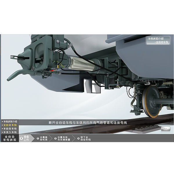
2) Teaching of coupler disassembly and installation process
- disassembly and assembly of fully automatic coupler
- disassembly and assembly of semi-automatic coupler
- disassembly and assembly of semi-permanent coupler
3. Door teaching function
1) Teaching of door structure and mechanical transmission principle
a) Overview of door
b) Passenger compartment door mechanical structure
- door transmission mechanism
- left and right door leaves
- finger guard rubber
- upper guide r*l and guide wheel
- lower guide r*l
- lower swing arm roller
- fixing pin and bracket
- cut-off lock
- cable
- emergency inner door opening device
- emergency outer door opening device
c) Mechanical transmission principle
2) Teaching of door disassembly and installation process
- door machine disassembly
- door machine installation
4. Mounting frame teaching function
1) Teaching of bogie structure and working principle (including teaching of tr*ler bogie and EMU bogie structure)
a) Bogie overview
b) Bogie mechanical structure
- frame
- wheelset -
primary suspension -
secondary suspension -
unit brake -
ATC antenna
- signal transmission sensor
- central traction connection device
- WSP speed sensor
- single carbon brush grounding device
- double carbon brush grounding device
- ATC speed sensor
- motor
c) Transmission principle
2) Teaching of bogie disassembly and installation process
- bogie vehicle disassembly and assembly
- wheelset disassembly and assembly
- primary suspension disassembly and assembly -
axle box end equipment disassembly and assembly -
motor disassembly and assembly
- secondary suspension disassembly
and assembly - unit brake
5. Pantograph teaching function
1) Teaching of pantograph structure and pantograph r*sing principle
a) Pantograph overview
b) Pantograph mechanical structure
- chassis
- lower bracket
- upper bracket
- coupling rod
- pantograph head
- parallel guide rod - pantograph r*sing mechanism - hydraulic shock absorber - electric pantograph lowering device - locking hook - electric control box - flexible shaft, flexible shaft connector, manual rocker c) Principle of pantograph lifting 2) Teaching of pantograph disassembly and installation process flow - disassembly and installation of pantograph on vehicle - assembly and disassembly of pantograph 6. Teaching function of brake module 1) Teaching of brake module structure and brake principle (*r supply and brake module, brake control module) a) Overview of brake module b) Mechanical structure of *r supply and brake module - *r compressor - *r dryer - EP brake control panel - brake control electronic unit - *r cylinder - relay c) Braking principle of brake module 2) Teaching of brake module disassembly and installation process flow - disassembly and installation on vehicle - disassembly and installation of *r compressor - disassembly and installation of *r dryer - disassembly and installation of brake control electronic unit - disassembly and installation of EP brake control panel - disassembly and installation of *r cylinder III. Tr*ning function 1. Replace the desiccant of *r dryer 2. Remove the *r desiccant 3. Change the oil of *r compressor 4. Replace the *r filter 5. Replace the *r compressor 6. Replace the motor 7. Replace the brake shoe of unit brake system 8. Replace the unit brake motor 9. Change the oil of gearbox 10. Install the wheelset IV. Examination and management function 1. Examination function: -Student login - Candidate answering questions - Candidate submitting papers - Automatic scoring 2. Examination organization and management function
-Question bank management (theoretical questions and operational questions)
-Test bank management, test paper distribution
-Examinee management
-Student score statistics and score EXCEL report export
3.Theoretical questions: Teachers can make their own questions and import them into the system.
4.Operational questions:
-Replace the desiccant of the *r dryer -Remove
the *r desiccant
-Change the oil of the *r compressor
-Replace the *r filter -Replace the *r compressor -Replace the motor
-Replace the brake shoe of the unit brake system -Replace the unit brake motor -Change the oil of the gearbox -Install the wheelset
 Wechat scan code follow us

24-hour hotline+86 18916464525

Phone18916464525
ADD:Factory 414, District A, No. 6, Chongnan Road, Songjiang Science and Technology Park, Shanghai ICP: Sitemap