DYRGZN-10 Machine Vision Teaching Experimental Device
Release time:2024-07-03 17:30viewed:times
Features and Advantages
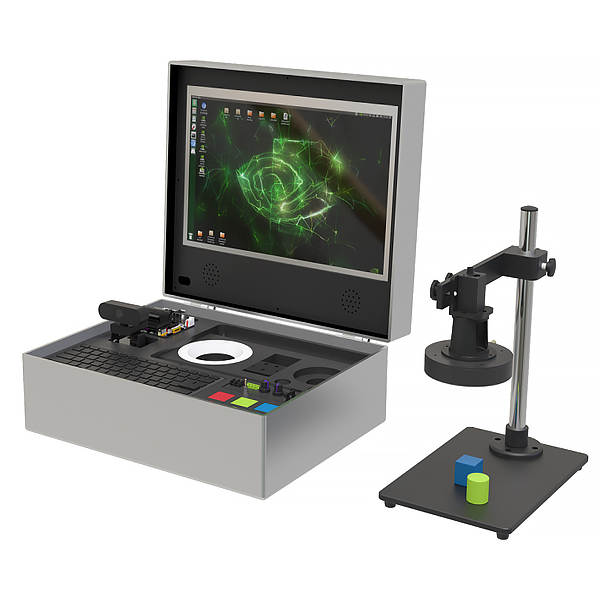
(1) Ready to use out of the box. Deploy edge computing terminals, equipped with 17-inch high-definition IPS touch screen, support ten-point touch, internal storage cells, support keyboard, mouse, power adapter, and storage of experimental teaching *ds. It is ready to use after power-on, and users do not need to configure any peripherals.
(2) Support two development environments. The experimental software provides two development environments: jupyter notebook and VS2015. Jupyter notebook uses Python programming language, and VS2015 uses C++ programming language. Users can choose according to actual needs to meet the teaching requirements of different colleges and universities.
(3) Dual vision system design. It includes a standard machine vision system and a pan-tilt vision system, which can carry out machine vision experiments in static and dynamic environments.
(4) Open source code. The entire software framework and algorithm-level source code are open. Students can conduct basic course tr*ning of application and verification nature at the code level through parameter adjustment, code filling, etc., or refer to the experimental guide, write code by themselves, and conduct relatively complex project tr*ning. Teachers can rely on this platform for in-depth secondary development.
M*n functional modules of the system
1. Edge computing terminal
The edge computing terminal uses NVIDIA's Jetson Nano processor, which has GPU computing capabilities. It can be used as an edge computing terminal (i.e., a small computer) and can also perform analysis and calculations related to digital image processing based on deep learning. By deploying relevant software and frameworks such as the visual system SDK, Python, and OpenCV in the processor, as well as communication protocols with external devices, students can complete a series of functions from visual system hardware construction, image acquisition, image processing, to experimental process design and demonstration, to the linkage control of the visual system and external devices, without the need to configure a separate computer.
The m*n technical parameters of the edge computing terminal are as follows:
(1) Processor: 64-bit quad-core CORTEX-A57, 128-core MAXWELL GPU;
(2) Memory: 4GB LPDDR, onboard storage: 128GB;
(3) Interface: USB3.0×4, Micro USB×1, HDMI×1, RJ45×1, DC5.5×2.1 power interface;
(4) Integrated Linux, Python and other operating environments, supporting the development and learning of algorithms, hardware, and applications such as digital image processing, machine vision, and deep learning.
2. Static vision system
The static vision system is a set of standard industrial-grade vision systems, including industrial cameras, lenses, LED light sources, light source controllers, etc., which are integrated through visual brackets to provide a hardware environment for practical tr*ning for all static target detection, analysis, and processing.
The structure of the visual system is as follows:
The m*n hardware of the visual system is as follows:
(1) Industrial camera
sensor model: Sharp RJ33;
pixel size: 3.75 µm×3.75 µm;
target surface size: 1/3”;
resolution: 1280×960;
frame rate: 30 fps;
exposure time: 34μs~1sec;
black and white/color: color;
interface: GiGE.
(2) Industrial lens
Focal aperture: fixed focal length;
aperture: manual aperture;
pixel level: 6 million pixels, FA lens;
focal length: 12mm;
F number: F2.8~F16.
(3) LED light source
Light source category: 30-degree ring light source;
LED type: SMD LED;
color: white;
color temperature: 6600K;
power: 14.4W.
3. Dynamic vision system (two-degree-of-freedom gimbal)
The dynamic vision system can transmit video or images online, transmit scene information to the edge computing terminal in real time for processing, and display the results through an external display device. Scene information includes faces, pedestrians, license plates, and other target objects to be detected. After identifying the target, it can follow the movement and carry out application-oriented comprehensive tr*ning related to pedestrian tracking, face recognition and tracking, license plate recognition, etc.
The system is m*nly composed of a two-degree-of-freedom gimbal and a camera;
sensor type: 2MP CMOS;
video format: PAL/NTSC;
maximum resolution: 1920×1080;
video frame rate: 1920×1080@30, 25fps;
lens: fixed focus 3.6mm;
field of view: horizontal 80.3°, vertical 50.8°, diagonal 88.7°.
4. High-definition display screen
Adopts a 17-inch high-definition touch screen;
the m*n technical parameters of the screen are as follows:
narrow frame design, 1920×1080 high-definition resolution;
IPS hard screen, tempered glass panel, 99% RGB, 178° wide viewing angle;
supports NVIDIA, Windows, Raspberry Pi and other operating systems, ten-point touch;
interface: USB, HDMI, power supply.
5. Single-chip microcomputer , PLC programmable design and control virtual simulation software (copyright certificate and demonstration video are required):
1) This software is developed based on Unity3D, with built-in experimental steps, experimental instructions, circuit diagrams, component lists, connection lines, power on, circuit diagrams, scene reset, return and other buttons. After the connection and code are correct, the three-dimensional machine tool model can be operated through the start/stop, forward movement, and reverse movement buttons . When the line is connected, the three-dimensional machine tool model can be enlarged/reduced and translated.
2) Relay control: Read the experimental instructions and enter the experiment. By reading the circuit diagram, select relays, thermal relays, switches and other components in the component list and drag and drop them to the electrical cabinet. The limiter is placed on the three-dimensional machine tool model. You can choose to cover the cover. Some component names can be renamed. Then click the connection line button to connect the terminals to the terminals. After the machine tool circuit is successfully connected, choose to turn on the power and operate. If the component or line connection is wrong, an error box will pop up, and the scene can be reset at any time.
3) plc control: the experiment is the same as relay control, with the addition of PLC control function. After the connection is completed, press the PLC coding button to enter the program writing interface, write two programs, forward and reverse, with a total of 12 ladder diagram symbols. After writing, select Submit to verify the program. After successful verification, turn on the power to operate. Errors in components, line connections, and code will pop up prompt error boxes, and the scene can be reset at any time.
4) MCU control: the experiment is the same as relay control, with the addition of MCU control function. After the connection is completed, press the C coding button to enter the programming interface, enter the correct C language code, and submit the verification successfully. Turn on the power to operate. Errors in components, line connections, and code will pop up prompt error boxes, and the scene can be reset at any time.
III. Experimental project requirements:
V. Practical tr*ning projects
1. Basic experiment: Python language programming
(1) Python integrated development environment construction, software installation experiment
(2) Python programming experiment: Calculate the factorial of any input integer
(3) Python programming experiment: Tower of Hanoi problem
(4) Python programming experiment: Use Monte Carlo method to calculate the approximate value of pi
(5) Python programming experiment: Use Numpy to perform t-test
(6) Python programming experiment: Use PIL to read, display and process images
(7) Python GUI programming experiment: Matplotlib data visualization
(8) Python GUI programming experiment: dynamic clock design
2. Basic experiment: digital image processing
(1) Algebr*c operation of images
(2) Image transformation
(3) Image segmentation
(4) Image smoothing
(5) Image enhancement
(6) Color image processing
(7) Morphological processing
(8) Edge detection
(9) Line and circle detection
(10) Triangle and rectangle detection
3. Basic experiment: machine vision
(1) Visual system construction and hardware operation
(2) Image acquisition and display
(3) Visual positioning
(4) Visual system calibration
(5) Color recognition
(6) Shape recognition
(7) Measuring object size
(8) Object presence detection
4. Course design: Face recognition system
(1) Able to input face data;
(2) Able to realize identity authentication;
(3) Has a dedicated user interface.
5. Course design: Shape recognition system
(1) Able to recognize flat color graphics, such as circles, rectangles, triangles;
(2) Able to recognize three-dimensional graphics of different sizes, such as basketballs, footballs, and volleyballs;
(3) Has a dedicated user interface.
6. Course Design: Object Defect Detection System
(1) Can pre-process objects;
(2) Can detect whether there are defects and extract defect features;
(3) Can output the size of the defect and determine whether the target is qualified.
7. Course Design: ID card character recognition system
(1) Can segment the ID card area in the field of view;
(2) Can find the area where the characters are located;
(3) Can segment the characters one by one, accurately recognize them, and then display them.
8. Course Design: License Plate Detection and Recognition System
(1) Can extract specific frame images from the video stream, pre-process them, and filter out interference information;
(2) Can locate the license plate position from the image;
(3) Recognize the license plate information and output it to the interface.
9. Course Design: Seed Counting and Grading System
(1) It can pre-process images and filter out interference information;
(2) It can segment different seeds and count the number of valid seeds;
(3) It can identify the characteristics of seeds one by one and grade seeds according to the classification criteria.


 Wechat scan code follow us
