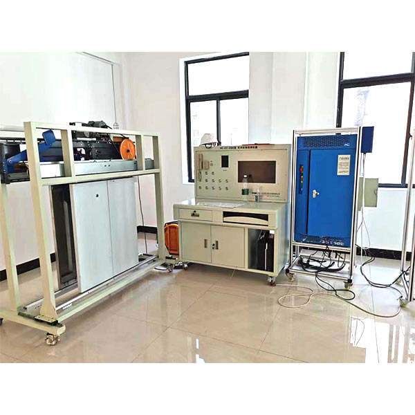
DYDT-2021 Elevator Fault Troubleshooting and Detection Simulation Experimental Device
Release time:2024-07-02 02:30viewed:times
1.1. M*n technical parameters of the control cabinet
(1) The elevator control cabinet must be a real elevator control cabinet;
(2) Working power supply: three-phase five-wire AC380V±7% or single-phase AC220V±4%;
(3) Control mode: integrated controller;
(4) Rated power: 5.5KW.
1.2. M*n technical parameters of the traction machine
(1) The traction machine is a real elevator traction machine;
(2) The traction machine must obt*n the "Special Equipment Type Test Certificate" in accordance with the requirements of the national standard GB 7588-2003 "Safety Specifications for Elevator Manufacturing and Installation", and the owner shall check it when it is supplied;
(3) Rated voltage: AC380V±7% or AC220V±4%;
(4) Traction device: permanent magnet synchronous traction machine or asynchronous geared traction machine used in the m*nstream domestic industry;
(5) Rated power: not more than 7.5KW;
(6) Rated load: not more than 800Kg;
(7) Rated speed: not more than 1.0m/s.
1.3. M*n technical parameters of elevator testing and debugging device
(1) Power supply voltage: AC380V±7% or AC220V±4%.
(2) The floor display in the car adopts a 7-inch multimedia LCD.
(3) The control device adopts a Monarch integrated machine.
(4) The direction of the traction machine can be displayed by the indicator light.
(5) Use real elevator car internal selection buttons and floor call buttons.
(7) Test object: integrated controllers used in the m*nstream domestic industry (reference brands: Monarch, New Step, Blue Light)
Control cabinet test bench m*n functions:
(1) Can provide the control cabinet with internal selection and external call instructions for the 1st to 2nd floors;
(2) Can provide the control cabinet with simulated shaft information for the 1st to 2nd floors, and the simulated shaft information can be programmed through software (the elevator control cabinet control device uses Monarch integrated machine);
(3) Can interact with the control cabinet to exchange elevator door opening and closing instructions and feedback signals;
(4) Can interact with the control cabinet to exchange overload, full load, locked elevator, fire , driver and other signals;
(5) The incoming power supply voltage is displayed digitally, with wrong phase and missing phase protection; (
6) The incoming m*n power supply of the control cabinet is controlled by the test bench, and the m*n power supply can be easily cut off in an emergency;
1.4. M*n technical parameters of the "floor car door opener" equipment
M*n components: door machine structure frame (including door frame), door machine controller and AC variable frequency door motor , door machine demonstration device components (including but not limited to m*n wires and cables), etc.
1) Working power supply: single-phase AC220V ±4%, 50Hz;
2) Door opening size: not more than 800mm;
3) Door opening form: center split double leaves, door leaf height not higher than 1200mm;
4) Drive control: domestic m*nstream brand;
5) External dimensions: not more than 1600*1800*500 mm (W*H*D)
6) Adopts the domestic m*nstream structure type, and is completely composed of real elevator door mechanisms and components.
7) The floor door and car door can be separated, adjusted and tr*ned separately, and can be combined for hall door and car door linkage tr*ning.
8) Use electrical or mechanical interlocking to prevent misoperation. Safety signs, signals and displays are clear and easy to identify to prevent safety accidents caused by human misoperation.
1.5. The components of the elevator electrical tr*ning and assessment device
use a completely real machine room power box, car top inspection box, car top junction box, pit inspection box, pit switch box, shaft lighting, machine room lighting, etc. that are 1:1 on the elevator.
1.6. The electrical fault rapid setting and recovery system
meets the needs of professional skill appr*sal and competition at the same time, and has no less than 40 typical elevator electrical fault setting switches.
1.7 Mechanical assembly and bench assembly virtual simulation software (provide copyright certificate and on-site demonstration): This software is developed based on unity3d, with 6 levels of image quality optional, and has reducers, shaft system structure design and virtual disassembly and assembly, common mechanical mechanism design and simulation, mechanism resource library, typical mechanical mechanism (virtual disassembly and assembly of gasoline engine), the software is an integral software, not a separate resource.
A. The reducer design and virtual disassembly and assembly interface can select worm bevel gear reducer, two-stage unfolded cylindrical gear reducer, bevel cylindrical gear reducer, coaxial cylindrical gear reducer, bevel gear reducer, and one-stage cylindrical gear reducer.
Worm bevel gear reducer: After entering the software, the assembly content will be played automatically, and each step in the video has text descriptions.
Secondary unfolded cylindrical gear reducer: After entering the software, the content will be played in the form of a video. The video content should include: part name (scan the QR code to see the part name), disassembly demonstration (including disassembly, assembly), virtual disassembly (including the whole, low-speed shaft, medium-speed shaft, high-speed shaft, box cover, box seat)
bevel cylindrical gear reducer, coaxial cylindrical gear reducer, bevel gear reducer, first-stage cylindrical gear reducer: click to enter and automatically jump to the edrawings interface, modelAll of them are 3D models. By clicking on the parts, the names of the parts are displayed. They can be rotated 360°, enlarged, reduced, and translated. At the same time, the entire reducer can be disassembled and assembled by moving the parts function. At the same time, the home button can be selected to return to the initial state of the reducer. The bevel gear reducer and the first-level cylindrical gear reducer have added the function of inserting cross sections, and the cross sections can be freely dragged to observe the internal structure of the reducer.
B. The design of the shaft structure and the virtual disassembly and assembly interface can
select parts recognition, disassembly and assembly demonstration, and actual combat operation. 1. Part recognition: The 3D models and part names of helical gears, holeless end covers, couplings, coupling keys, shafts, gear keys, holed end covers, sleeves, and deep groove ball bearings are built in. Any part can be rotated 360°.
2. Disassembly and assembly demonstration: There are 2 built-in cases. When the mouse is moved to a cert*n part position (except the base and the bearing seat), the part is automatically enlarged and the part name is displayed. There are disassembly and assembly buttons. The function is automatically completed by the software to disassemble and assemble the shaft structure. All 3D scenes can be rotated 360°, enlarged, reduced, and translated.
3. Actual operation: The three-dimensional parts are neatly placed on the desktop. Students manually select the corresponding parts and move them to the shaft structure. The parts can only be installed when the placement order and position are correct. There is a restart button to facilitate students to repeat the virtual experiment. When the mouse moves to a cert*n part position (except the base and the bearing seat), the part is automatically enlarged and the part name is displayed.
C. Common mechanical mechanism design and simulation optional hinge four-bar mechanism design and analysis, I\II type crank rocker mechanism design and analysis, offset crank slider mechanism design and analysis, crank swing guide rod mechanism design and analysis, hinge four-bar mechanism trajectory synthesis, eccentric linear roller push rod cam , concentric linear flat bottom push rod cam.
1. Each mechanism should be able to input the corresponding parameters, and the software will automatically calculate the parameters, and can perform motion simulation and automatically draw curves.
D. The mechanism resource library can choose 11 types of planar connecting rod mechanisms, 5 types of cam mechanisms, 6 types of gear mechanisms, 8 types of transmission mechanisms, 11 types of tightening mechanisms, 6 types of gear tr*n mechanisms, and 8 types of other mechanisms (mechanical equipment simulation).
E. Virtual disassembly and assembly of gasoline engines can choose crankcase assembly and disassembly demonstration, crankcase virtual assembly, valve system assembly and disassembly demonstration, and valve system virtual assembly.
1. The crankcase assembly and disassembly demonstration and the valve system assembly and disassembly demonstration are equipped with disassembly buttons, assembly buttons, restart buttons, and decomposition observation buttons. When the mouse moves to a cert*n part position, the part is automatically enlarged and the part name is displayed. The function is automatically completed by the software to disassemble and assemble the shaft system structure. When the decomposition observation button is used, the three-dimensional model of the crankcase or valve system automatically displays an exploded view, which can be rotated 360° in all directions, enlarged, reduced, and translated.
2. The three-dimensional parts of the crankcase virtual assembly and the valve system virtual assembly are neatly placed on the desktop. Students manually select the corresponding parts and move them to the mechanism. The parts can only be installed when the placement order is correct and the position is correct. There is a restart button to facilitate students to re-conduct virtual experiments. When you move the mouse to cert*n parts, the part names are automatically displayed.
1.8. Tr*ning projects
Car door and hall door installation and debugging and troubleshooting
Fast and slow car debugging, program parameter setting and writing
Door lock circuit wiring and troubleshooting
Safety circuit wiring and troubleshooting
Shaftway switch wiring and troubleshooting
Control cabinet circuit troubleshooting
Car top circuit troubleshooting
(8) External call and internal selection troubleshooting


 Wechat scan code follow us
