Shanghai Daiyu Education Equipment Manufacturing Co., Ltd.
Language:


| Serial number | name | quantity | unit | Remark |
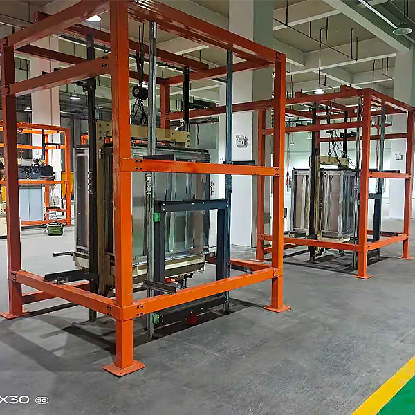
| 1 | Hoistway frame | 1 | tower | Steel structure |
| 2 | Guide r*l and car frame mechanism | 1 | set | |
| 3 | Electric hoist | 1 | tower | |
| 4 | Floor door leaf | 1 | set | |
| 5 | Door frame | 1 | set | Left and right pillars and door lintels, etc. |
| 6 | Landing door mechanism | 1 | set | |
| 7 | Door sill | 1 | strip | |
| 8 | Landing door sill bracket | 2 | indivual | |
| 9 | Toe guard | 1 | piece | |
| 10 | Car door | 1 | set | |
| 11 | Car door mechanism | 1 | set | Crossbars, inclined pull rods, door knives, inverters and motors , etc. |
| 12 | Car door sill | 1 | strip | |
| 13 | Mounting Accessories | 2 | set | 1 spare set |
| 14 | Installation and measuring tools | 1 | set | Level and measuring tape, etc. |
| 15 | Random Information | 1 | share | Tr*ning instructions and related drawings, etc. |
 Wechat scan code follow us

24-hour hotline+86 18916464525

Phone18916464525
ADD:Factory 414, District A, No. 6, Chongnan Road, Songjiang Science and Technology Park, Shanghai ICP: Sitemap