Shanghai Daiyu Education Equipment Manufacturing Co., Ltd.
Language:


| Serial number | name | quantity | unit | Remark |
| 1 | Escalator electrical truss system | 1 | set | Detachable and modular, easy to transport and install |
| 2 | Escalator support fixed steel frame | 1 | set | High quality square tube welding, thickness 2mm |
| 3 | Tr*ning table | 1 | set | 1500*700*750 |
| 4 | Tr*ning platform | 1 | set | 1400*250*700 |
| 5 | Escalator disassembly and assembly tr*ning tools | 1 | set |
| Serial number | content |
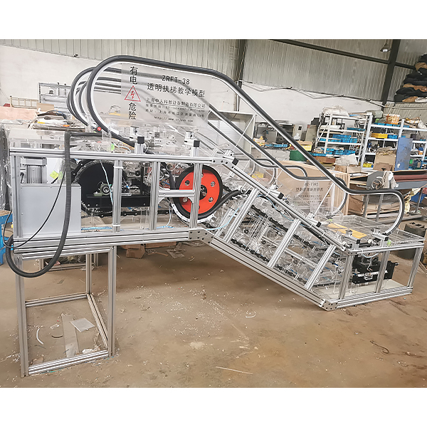
| 1 | Escalator structure truss: high-quality angle steel and square steel |
| 2 | Handr*l bracket profile: high quality square tube welding frame |
| 3 | W*nscoting: Transparent plexiglass |
| 4 | Inner cover: H*rline plexiglass material |
| 5 | Outer cover: H*rline plexiglass material |
| 6 | Apron board: H*rline plexiglass material |
| 7 | Steps: Plexiglas, Step width: 400mm |
| 9 | Handr*l: Black |
| 10 | Front plate and cover plate: organic glass material |
| 11 | Comb tooth protection: Synthetic resin (yellow) |
| 12 | Truss protection: 4mm transparent plexiglass plate |
 Wechat scan code follow us

24-hour hotline+86 18916464525

Phone18916464525
ADD:Factory 414, District A, No. 6, Chongnan Road, Songjiang Science and Technology Park, Shanghai ICP: Sitemap