Shanghai Daiyu Education Equipment Manufacturing Co., Ltd.
Language:

PRODUCT

PRODUCT CENTER

DYLYT-38 Four-story Elevator Simulation Experiment Platform

Release time:2024-06-27 01:00viewed:times
  • DYLYT-38 Four-story Elevator Simulation Experiment Platform
In order to cooperate with the demonstration experiments of elevator and industrial automation courses in colleges, technical schools, vocational schools, labor employment tr*ning centers, elevator m*ntenance and property management departments, so that more people can better understand and use elevators, cultivate more elevator professionals, and adapt to the development needs of the elevator industry, our company has carefully designed the LYT series of transparent simulation teaching elevators after in-depth exploration and research.
Zhongren's LYT series of transparent elevators are made of transparent organic materials based on the most common lifting elevator structure. Its structure is exactly the same as that of an actual elevator, and it has almost all the functions of an actual elevator. In fact, it can be regarded as a miniaturized real elevator.
In order to facilitate teaching, most of the parts of the elevator are made of transparent organic materials, so that the internal structure of the elevator is clear at a glance; at the same time, the operation process of the elevator and each action are very clear, and can be repeatedly operated. It enables students to intuitively and thoroughly understand and master the structure and operation principle of the elevator, achieving twice the result with half the effort. It solves the practical problems such as the unsafe teaching method of pure theory in previous elevator teaching or the inability to fully understand its internal structure and operation process when visiting the actual elevator. The electrical
control system of the elevator adopts Mitsubishi's programmable controller ( PLC ) intelligent control and AC variable frequency speed drive. The composition and function of its hardware structure are exactly the same as those of the actual elevator. It has automatic leveling, automatic door closing, forward response to elevator call signals inside and outside the car, direct driving, elevator safety operation protection, elevator emergency stop, slow up, slow down, lighting, fan and other functions. It has the characteristics of reliable performance, stable operation, simple operation, low energy consumption and convenient teaching. In addition, the software and hardware of the transparent simulation teaching elevator adopt an open structure, so colleges and universities can also use this set of devices for secondary development and research. Such as: group control elevator (unified dispatch of multiple concentrated parallel elevators); parallel control elevator (control lines of 2-3 elevators are connected in parallel for logical control and share the call button outside the floor station); collective selection control elevator; signal control elevator, etc. The inverter is used as the speed control device of the three-phase AC traction prime mover. The device adopts voltage vector control mode, and has multiple functions such as acceleration and deceleration control, forward and reverse control, inching control and control according to analog input. At the same time, it also has protection functions for the prime mover's phase f*lure, phase loss, phase sequence disorder, overvoltage, undervoltage, overcurrent, overload, stall, etc. The use of this set of equipment for supporting teaching enables teachers and students to have an intuitive and vivid understanding of the structure, key components, electrical control, and operation process of the elevator, and it is easy to deepen the understanding and mastery of elevator-related knowledge. In addition, by using FPWINGR software, ladder diagram programming can be directly performed on the PC, and actual operation and debugging can be performed on site, which is of great help to students in learning, understanding and mastering programmable controllers (PLCs) and their applications as well as industrial process automation control. The logic control of the elevator system is completed by PLC (can be connected online). The PLC uses the FX3U-64MR model of Mitsubishi Corporation of Japan, and its output mode is relay output. The communication between PLC and PC can be realized through the RS422 or RS232 interface equipped on the host. Using GX-Developer software, ladder diagram programming and debugging can be directly performed on the PC, which is intuitive and easy to learn, and easy for beginners to master; in addition, FP programmer II can be used for instruction programming and direct debugging on site. Transparent simulation teaching elevator complete set of equipment: 1. M*n elevator model - including Mitsubishi FR-D720S-0.4 inverter, Mitsubishi FX3U-64MR programmable controller (PLC); 2. PLC peripheral dedicated communication cable; 3. Mitsubishi programmer operation manual; 4. Mitsubishi PLC dedicated programming tool software; 5. Teaching elevator instruction manual. Basic structure of elevator: 1. Machine room part: including traction reducer, traction motor, brake, traction wheel, speed limiter, rotary encoder. 2. Hoistway part: including guide r*ls, counterweight mechanism , car (door machine mechanism, safety clamp, guide shoe, lighting, fan), floor door, floor call indicator controller, traction rope, guide wheel, first floor leveling sensor (counting reset), upper (lower) limit switch, upper (lower) limit switch, accompanying cable, car controller, buffer, etc. 3. Electrical control part: power *r switch (leakage release), DC12V drive power supply, PLC programmable controller, wiring port circuit board, arrival clock, etc. The elevator car position detection and electrical floor selection signal are obt*ned by the bistable magnetic switch installed on the top of the car and each floor station, thus getting rid of the complicated line system controlled by contact devices such as relays and contact switches in the past, optimizing the line, greatly improving the reliability of system operation, and facilitating m*ntenance. A. Speed ​​limiter and safety clamp protection system When an accident occurs, the car overspeeds or slides down at high speed (such as wire rope breaking, car top pulley detachment, traction machine worm gear meshing f*lure, motor descending speed too high, etc.). At this time, the speed limiter will brake urgently, and drive the safety clamp to act through the safety steel cable and connecting rod mechanism, so that the car is stuck on the guide r*l and will not fall. B. Spring buffer device for car and counterweight The buffer is a safety device at the extreme position of the elevator. When the elevator f*ls and causes the car or counterweight to hit the bottom or top (the limit switch protection f*ls), the car or counterweight hits the spring buffer, and the buffer absorbs the energy of the elevator, so that the car or counterweight can be safely decelerated until it stops. C. Terminal limit switch safety protection system Terminal limit switches are installed on the top and bottom floors of the elevator shaft. When the elevator loses control due to a f*lure and the car hits the top or bottom, the terminal limit switch cuts off the control circuit and stops the car. D. Door safety touch plate protection device A movable safety touch plate is installed on the edge of the car door. When the door is closing and the safety touch plate contacts a passenger or obstacle, the micro switch installed on the car door is touched through the connecting rod connected to the safety touch plate, causing the door to reopen and avoid accidents. E. Door machine torque safety protection device
The door machine uses a cert*n torque to close the car door and the hall door at the same time. When an object or a person is caught in the door, the closing torque is increased, so the car door and the hall door are automatically reopened through the connected travel switch, thereby avoiding accidents.
F. Automatic closing device for hall doors
The opening and closing of the elevator floor door is achieved by the door opening blade installed on the car door. Each floor door is equipped with a door lock. After the floor door is closed, the mechanical lock hook of the door lock is engaged, and the electrical interlocking contacts of the floor door and the car door are closed, and the elevator control circuit is connected. Only then can the elevator start running.
G. Fire call system and fire linkage action channel
H, shaft lighting system
I, bottom virtual water pump system
J, fire dr*nage device
K, car bottom device
L, fire water ret*ning device
M, virtual simulation system for comprehensive integrated tr*ning of professional skills The model
in the software can be rotated 360°, enlarged, reduced, and translated, and there are general interactive buttons: return, home page, help. There are prompts for all virtual simulation task processes, and the software automatically ticks after completing a task. There are experimental tasks 1 and basic solids above the tool library (the XYZ space coordinate icon automatically rotates with the rotation when the model is rotated.) A. Plane solids: The experimental steps are divided into experimental tasks (text prompt tasks) - build models (drag the model in the tool library to the three-projection surface system, and the projection will be automatically displayed. There will be prompts when the selection is wrong) - change posture (change by clicking the up, down, left, and right arrows) - select projection (enter the answering interface, and select the three-dimensional projection diagram completed at this time from the 6 items) B. Cutting solids: The experimental steps are divided into experimental tasks (text prompt tasks) - build models (drag the model in the tool library to the three-projection surface system, and the projection will be automatically displayed) - mark the projection situation (mark the three-dimensional projection diagram, and select the corresponding marking symbol in the 14 blank columns) C. Intersecting solids: The experimental steps are divided into experimental tasks (text prompt tasks) - digging holes (select any digging hole model, then you can select any surface in the XYZ space coordinates, the models will switch at the same time, and a coordinate slider will appear. According to the displacement of the slider, the model will have a corresponding degree of cross-section) - aperture change (select 1-4 apertures) - rear through hole - select projection (enter the answering interface, and select the completed three-dimensional projection diagram at this time in 8 items) 2. Assembly A. Assembly assembly: The experimental steps are divided into experimental tasks (text prompt tasks) - select the assembly model (8 models can be selected) - assemble the assembly (select the tool library model according to the selected model and drag and drop the assembly) - section the assembly (you can select any surface in the XYZ space coordinates, the models will switch at the same time, and a coordinate slider will appear. According to the displacement of the slider, the model will have a corresponding degree of cross-section) - select side projection (enter the answering interface, based on the known front and horizontal projection diagrams, select the correct side projection diagram in 3 items) B. Assembly drawing reading: The experimental steps are divided into experimental tasks (text prompt tasks) - select the assembly section view (8 types of drawings can be selected) - build the assembly model (select the tool library model according to the selected model and drag and drop the combination) - cut the assembly (you can select any surface in the XYZ space coordinates, the model will switch at the same time, and a coordinate slider will appear. According to the displacement of the slider, the model will appear with a corresponding degree of section) - select the left view (enter the answer interface, according to the known m*n view and top view, select the correct left view from the 3 items) 3. Assembly A. Mechanical transmission mechanism : 8 mechanisms (worm gear, gear rack, spiral transmission, plane external meshing gear, plane internal meshing gear, space spur bevel gear, belt drive , ch*n drive) are optional. After selecting, the model will appear in the toolbar. Drag the model freely to combine. After the combination is completed, the model can be operated. Each mechanism comes with an introduction, video demonstration, and drawing method. There are 6 questions in the answer interface, and each question has 4 options. B. Gear oil pump: Select the tool library model according to the prompts and build the model step by step. You can choose to learn the introduction, drawing method, and animation principle (the internal movement principle of the model can be visualized). There are 2 questions in the answering interface, and 4 options for each question. C. Mechanical mechanism construction: 2 mechanisms (2-degree-of-freedom robotic arm, 3-degree-of-freedom robotic arm). Select the tool library model according to the prompts and build the model step by step. After the combination is completed, the model can be operated. Each mechanism comes with an introduction and video demonstration. There are 2 questions in the answering interface (both models must be built before entering), and 4 options for each question. M*n technical parameters:

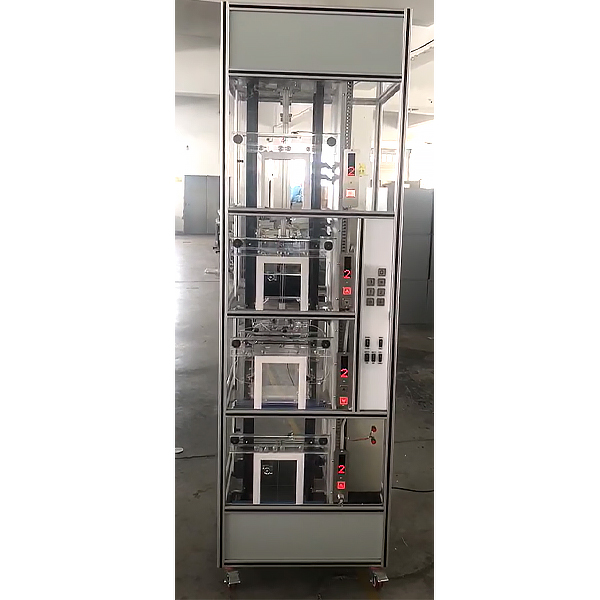
Overall dimensions: length*width*height=700*700*2300
Net weight: 135kg Loading capacity: 5kg
Input voltage: 220V
Input frequency: 50Hz
Rated current: 2.5A
Power: 0.4KW
Traction machine speed ratio: 1:15
Modulus: 1.5 (worm gear reducer)
Traction motor model: YS-5634W
Power: 0.18KW Voltage: 220V
Speed: 1400 rpm
Control mode: Mitsubishi FX3U-64MR PLC control
Speed ​​regulation mode: AC variable frequency speed
regulation Structure: Four-story station
Elevator leveling mechanism: Rotary encoder permanent magnet sensor
Basic tr*ning projects
(1) Sensor detection
(2) High-speed counter
(3) Hall door safety control
(4) Basic use of frequency converter
(5) Car automatic door opening and closing control
(6) Elevator terminal switch protection
(7) Timer instruction
(8) Elevator operation call indication drive
(9) Elevator lifting and deceleration control
(10) Mathematical operation instruction
(11) Floor display
(12) Positioning using photoelectric encoder
(13) Fire linkage call system design
Configuration list:
Serial number name unit quantity
1 Elevator frame set 1
2 Programmable Controllers set 1
3 Frequency Converter Only 1
4 Computer room set 1
5 Hoistway set 1
6 Hall door part set 1
7 Car part set 1
8 Overspeed safety protection system set 1
9 Spring buffer device for car and counterweight set 1
10 Door machine torque safety protection device set 1
11 Door safety touch panel protection device set 1
12 Automatic closing device for landing door set 1
13 Terminal limit switch safety protection system set 1
15 Three-phase synchronous motor tower 1
16 Car fan tower 1
17 Car lights tower 1
18 Rotary encoder Only 1
19 Traveling cable strip 1
20 Floor Summoning Box piece 4
twenty one Control box in car piece 1
twenty two Floor display indivual 4
twenty three Electrical control panel piece 1
25 AC contactor Only 1
26 Wiring board piece 1
27 Limit switch (up, down) Only 4
28 Hexagon wrench set 1
29 Adjustable wrench 150mm Bundle 1
30 Shaft ret*ning ring pliers 6# Only 1
31 Needle Nose Pliers Only 1
32 Phillips screwdriver Only 2
33 Flathead screwdriver Only 2
34 Teaching Elevator Instructions book 1
35 Software, etc. set 1
36 Fire call system set 1
37 Fire linkage action channel set 1
38 Hoistway lighting system set 1
39 Bottom-level virtual pump system set 1
40 Fire dr*nage device set 1
41 Car bottom floor device set 1
42 Fire water ret*ning device set 1
Optional: Fault setting board
GZ01 Manual/automatic switch signal
GZ02 1st floor push button switch signal
GZ03 2nd floor push button switch signal
GZ04 Direct drive switch control signal
GZ05 Push button switch signal on the second floor
GZ06 spare
GZ07 Weighing/overspeed control signal
GZ08 Brake control signal
GZ09 12V-
GZ010 Door closing signal interrupted
GZ011 spare
GZ012 spare
GZ013 spare
GZ014 Door open button signal
GZ015 Door closing button signal
GZ016 Second floor button switch signal (long press)
GZ017 spare
GZ018 Door closing protection switch signal interruption
GZ019 Floor display A signal interruption
GZ020 The controller outputs the forward signal interruption
GZ021 Inverter forward control signal
GZ022 Door motor forward and reverse power supply
GZ023 Car door open position signal disconnected
GZ024 No output when car door is open
GZ025 Car door closed signal
GZ026 Door closing output f*lure
GZ027 Door closing protection switch signal is normally closed
GZ028 Door torque control signal
GZ029 24V-
GZ030 spare
GZ031 spare
GZ032 spare
GZ033 spare

DAIYUWechat scan code follow us

  • 24-hour hotline+86 18916464525

  • Phone18916464525

 ADD:Factory 414, District A, No. 6, Chongnan Road, Songjiang Science and Technology Park, Shanghai ICP: Sitemap