DYLR-10 air conditioning refrigeration and heating assessment experimental platform
Release time:2024-06-19 08:30viewed:times
1. Overview The
"Air Conditioning Refrigeration and Heating Tr*ning and Assessment Device" is a product developed in accordance with the requirements of the Ministry of Education's "Revitalizing the 21st Century Vocational Education Curriculum Reform and Textbook Construction Plan", with competence as the basis and employment as the orientation, closely combined with production practice and the skill requirements of occupational positions, and in accordance with the teaching and tr*ning requirements of vocational education. It is suitable for teaching and tr*ning devices such as refrigeration technology, refrigeration fluid machinery , principle and m*ntenance of household refrigeration equipment, cold storage and refrigeration technology, and refrigeration equipment rep*rman (primary, intermediate, and advanced) tr*ning in higher vocational colleges and vocational schools. Cultivate skilled application-oriented talents who master the professional theoretical knowledge and professional practical skills of *r conditioning and refrigeration technology, and engage in technical upgrading, transformation design, installation, commissioning, m*ntenance, rep*r, and technical management of *r conditioning, refrigeration equipment and systems.
2. Device Features
1. The system uses a real refrigeration unit, which is in line with actual teaching. The entire *r conditioning system is real and complete, and the overall structure and performance are exactly the same as those of the remote control heat pump *r conditioner on the market. 1. It has functions such as cooling, heating, ventilation, dehumidification, temperature, wind speed selection, timing, wind sweep control, sleep, and automatic
. 2. The whole tr*ning device integrates refrigeration system, electrical control system, and fault simulation system. The system is real and complete, with clear and compact structure, consistent with the actual *r-conditioning refrigeration system and electrical system, and meets the requirements for tr*ning
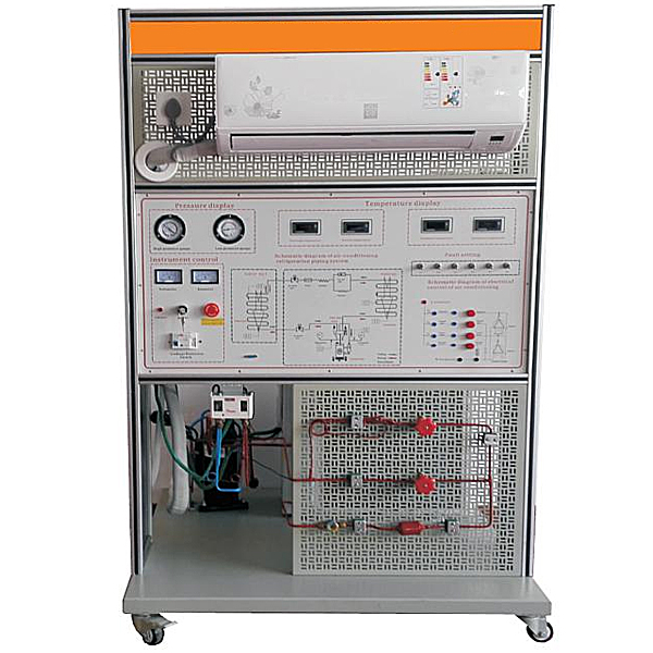
. 3. The tr*ning device intuitively displays the system structure and working principle of the heat pump split *r conditioner. The structure of the refrigeration cycle system and the m*n components can be clearly seen. The system is also equipped with AC voltmeter, AC ammeter, temperature gauge, vacuum pressure gauge, and the schematic diagram of the entire heat pump *r-conditioning system on the back; there is a plexiglass plate on the left side of the m*n panel, through which you can see the components and layout of the *r conditioner m*n control panel; the control system schematic is printed in the middle of the m*n panel, and corresponding test points are set; it is convenient for teaching demonstrations and students to understand and master textbook knowledge. In addition, a sight glass is installed in the pipeline to observe the state of the refrigerant. The high-pressure pipeline is the red part, the low-pressure pipeline is the blue part, and the corresponding parts are labeled with names.
4. The device is equipped with an outdoor unit component electrical control circuit wiring area, which can complete electrical connections, compressor winding judgment, etc., which is conducive to students applying theory to practice and cultivating students' practical operation skills.
5. The fault setting can be simulated. Students can analyze the possible causes of the fault according to the process, determine the scope of the fault, and troubleshoot. It is conducive to the development of skills identification and assessment work
III. Technical performance
1. Input power: single-phase three-wire AC220V ±10% 50Hz
2. Device capacity: <1kVA
3. Dimensions: 1100mm×700mm×1610mm
4. Refrigerant type: R410
5. Safety protection: with leakage voltage and leakage current protection devices, safety meets national standards
IV. Equipment configuration function
The tr*ning device consists of a control panel, a tr*ning table, an *r-conditioning outdoor unit, an *r-conditioning indoor unit, a measuring instrument, a simulated fault detection unit, a simulated fault box, etc.
1. Tr*ning table : aluminum alloy double-layer matte dense gr*n spray structure, aluminum panel. The desktop is a fireproof, waterproof, wear-resistant high-density board with a solid structure. The structure of the refrigeration system pipeline can be observed on the back of the device, which is used to simulate the electrical troubleshooting and setting of the *r conditioner.
2. There is a teacher fault setting unit, and the teacher can set dozens of faults in the setting unit.
3 Student troubleshooting unit, after the teacher sets the fault, the student can analyze the fault and detect the unit and location where the fault occurs. The data analysis system can also be used to automatically test and eliminate faults.
4. One set of *r conditioning unit: including some necessary components for heat pump split *r conditioners, such as evaporator, condenser, compressor, four-way valve, etc. The pipeline is also equipped with control valves and other components necessary for practical tr*ning
5. AC power control unit: single-phase three-wire 220V AC power supply, one AC voltmeter, measuring range 0~250V, used to monitor the grid voltage; one AC ammeter, measuring range 0~5A, used to observe the system startup current and monitor the normal working current of the system, the leakage protector controls the total power supply of the control panel, and the power supply of the control panel is controlled by the key switch
6. Refrigeration system pressure detection unit: 2 vacuum pressure gauges are provided, with measuring ranges of -0.1~1.5MPa and -0.1~5.5MPa respectively, which can display the pressure on the low-pressure side and high-pressure side when the system is working
7. Temperature detection unit: 4 temperature gauges are provided, with three-and-a-half-digit display, which respectively measure the ambient temperature, outlet temperature, condenser temperature and evaporator temperature
8. Simulation fault settings: The simulation fault settings are diversified. The refrigeration fault settings include evaporator dirty blockage, condenser dirty blockage, capillary dirty blockage, capillary ice blockage; the electrical fault settings include power supply circuit, temperature sensor circuit, drive circuit, compressor protection circuit, indoor fan speed control circuit and other fault points.
9. Single-chip microcomputer , PLC programmable design and control virtual simulation software:
This software is developed based on unity3d, with built-in experimental steps, experimental instructions, circuit diagrams, component lists, connection lines, power on, circuit diagrams, scene reset, return and other buttons. After the connection and code are correct, the 3D machine tool model can be operated through the start/stop, forward motion, and reverse motion buttons . When the line is connected, the 3D machine tool model can be enlarged/reduced and translated.
1. Relay control: Read the experiment guide and enter the experiment. By reading the circuit diagram, select relays, thermal relays, switches and other components in the component list and drag and drop them into the electrical cabinet. The limiter is placed on the three-dimensional machine tool model. You can choose to cover the lid. Some component names can be renamed. Then click the connect line button to connect the terminals. After the machine tool circuit is successfully connected, choose to turn on the power and operate. If the component or line connection is wrong, an error box will pop up. The scene can be reset at any time.
2. PLC control: The experiment is the same as relay control, and the PLC control function is added. After the connection is completed, click the PLC coding button to enter the program writing interface. Write two forward and reverse programs. There are a total of 12 ladder diagram symbols. After writing, select Submit to verify the program. After successful verification, turn on the power to operate. Error boxes will pop up for component, line connection, and code errors. The scene can be reset at any time.
3.Single chip microcomputer control: The experiment is the same as the relay control, with the single chip microcomputer control function added. After the connection is completed, enter the programming interface through the C coding button, enter the correct C language code, submit the verification successfully, turn on the power to operate, and the error box will pop up for components, line connections, and code errors. The scene can be reset at any time.
Five *r conditioner operation data analysis system
1. The data test system can quickly measure the circuit part where the *r conditioner f*lure occurs
2. It can detect whether the *r conditioner has communication data
3. It can simulate the communication data between the outdoor unit and the indoor unit of the *r conditioner to control the indoor unit
4. Measure the operating status of the machine and read the real-time temperature of each sensor .
5. Can measure the operation data of variable frequency *r conditioner
6. Can simulate the communication data between the outdoor unit and the indoor unit of the *r conditioner to control the outdoor unit
VI. Fault description
1. Disconnect N2 coil: simulate the secondary side N2 of transformer T is open, the whole machine does not work
2. Disconnect the bridge rectifier: simulate the bridge rectifier bridge ring +12V has no output, the whole machine does not work
3. Disconnect the output of 7805 voltage regulator: simulate the 7805 voltage regulator is broken +5V has no output, the whole machine does not work
4. Disconnect the infrared receiving tube 1 pin: simulate the infrared receiving tube has no power input, can not be remotely controlled
5. Disconnect the X105 temperature sensor resistor: simulate the compressor overheating, thermal protection fault
6. The outdoor unit pipe temperature sensor is broken, the *r conditioner does not work, and the fault code is displayed
7. The outdoor unit ambient temperature sensor is broken, the *r conditioner does not work, and the fault code is displayed
8. The outdoor unit pressure protection sensor is broken, the *r conditioner does not work, and the fault code is displayed
9. The indoor unit stepper motor is broken, the *r conditioner works, and the wind is not swept.
10. The internal pipe temperature sensor is broken, the *r conditioner does not work, and the fault code is displayed.
11. The indoor sensor is broken, the *r conditioner does not work, and the fault code is displayed.
12. The indoor fan adjustment circuit is broken, the *r conditioner does not work, and the fault code is displayed.
13. Disconnect the two sets of coils of the stepper motor: simulate the two sets of coils of the stepper motor are open.
14. Disconnect the relay RY4 coil: simulate the relay RY4 coil is broken, and the auxiliary heater does not work.
15. Disconnect the relay RY2 coil: simulate the relay RY2 coil is broken, and the outdoor fan does not rotate.
16. Disconnect the relay RY7
coil: simulate the relay RY7 coil is broken, and the indoor fan does not rotate at low speed. 17. Disconnect the relay RY6 coil: simulate the relay RY6 coil is broken, and the indoor fan does not rotate at medium speed.
18. Disconnect the relay RY5 coil: simulate the relay RY5 coil is broken, and the indoor fan does not rotate at high speed.
19. Disconnect the relay RY1 coil: simulate the relay RY1 coil is broken, and the compressor does not work.
20. Disconnect the relay RY3 coil: simulate the relay RY3 coil is broken, and the electromagnetic four-way valve does not work.
21. The communication f*lure between the outdoor and indoor units of the variable frequency *r conditioner
22. Simulate the fluctuation of the grid voltage: simulate the grid voltage regulator
is adjustable VII. Tr*ning projects
1. Basic skills tr*ning for junior technicians
2. Basic operation of special tools for refrigeration system
3. Welding of refrigeration system pipes
4. Leak detection of refrigeration system
5. Vacuuming and charging of refrigerant R410 in refrigeration system
6. Intermediate skills tr*ning (design, installation, commissioning and m*ntenance)
7. Circuit principle of *r conditioner m*n control board
8. Measurement of *r conditioner electrical components and system operation
9. Air conditioner f*lure and analysis
10. Air conditioner detection and f*lure analysis


 Wechat scan code follow us
