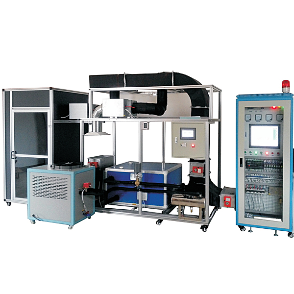
DYLR-TFG variable air volume central air conditioning system experimental platform
Release time:2024-06-18 19:00viewed:times
I. Overview
1. VAV is the abbreviation of Variable Air Volume. In the *r conditioning system, in order to cope with the change of terminal load, the *r volume is changed to adjust the delivery of cold/heat to meet the changing needs while the flow rate of cold/heat medium rem*ns unchanged. VAV (variable *r volume *r conditioning system) is a kind of system that adjusts the *r volume by changing the *r supply. Design standards, "Heating, ventilation and *r conditioning design specifications" (GBJ19-87-2003). "Ventilation and *r conditioning engineering quality inspection and evaluation standards" (GBJ304-2002) "Concise ventilation design manual" (GB50194-2002) "Compressor, fan, pump installation engineering construction and acceptance specifications" (JBJ29-2002) " Electrical installation engineering low-voltage electrical construction and acceptance specifications" (GB50254-96) " Comprehensive emission standard of *r pollutants " (GB16297-1996). "Environmental Air Quality Standard" (GB3095-1996), "Urban Area Environmental Noise Standard" (GB3096-93), " Building Design Fire Protection Code" (GB50016-2006), "Public Building Energy Saving Design Standard" (GB50189-2005).
2. The tr*ning device is also suitable for ordinary colleges, technical schools, vocational tr*ning schools, vocational education centers, appr*sal stations/institutes, refrigeration majors "Refrigeration Equipment M*ntenance Worker (Advanced)", "Refrigeration Equipment Principles and M*ntenance", "Refrigeration and Air Conditioning Equipment Operation, Installation and M*ntenance", "Central Air Conditioning Worker (Primary, Intermediate, Advanced)", "Household Refrigeration Equipment Principles and M*ntenance" and other courses.
2. Product parameters
1. The wind speed in the box branch pipeline is 6~8m/s, and the wind speed in the m*n pipeline is 8~14m/s; 6 universal input points (UI), 2 digital input points (BI), 2 analog output points (AO), 3 digital output points (BO) and 4 configurable output points (CO), which can measure the *r volume damper controller 4-20MA, and the pressure difference sensor 4-20MA.
2. Design *r volume of ventilation equipment: ventilation hood face wind speed: 0.3~0.8 m/s, single fume hood design *r volume 1500m3/h,
3. Ventilation times: ventilation times: 8~12 times/hour
4. Working environment: ambient temperature range is -5℃~+40℃, relative humidity <85% (25℃), altitude <4000m
5. Device capacity: <4.8kVA
6. Dimensions: 4000mm×1000mm×2000mm
7. Refrigerant type: R22
8. Safety protection: with leakage voltage and leakage current protection devices, safety meets national standards
9. Voltage: input power: 3800V±10% 50Hz
III. Product features
1. It has a real central *r conditioning system (VAV and fan coil + fresh *r system) and corresponding building automatic control system, and a completely real engineering environment. Let students conduct practical tr*ning on the components, functions, composition and principles of the building HVAC monitoring system. Through the client, the system can save the data and graphics of the system monitoring nodes, monitor and manage all the monitoring nodes on the network, and perform demonstration operations of the building *r conditioning water supply and boiler monitoring system, point meter recognition and wiring operation tr*ning between the DDC controller and various components, fault detection and elimination and other practical operations.
2. Adopting intelligent DDC control system, automatic water flow control (flow integral regulating valve) variable frequency control technology, intelligent variable frequency control system, to achieve the purpose of convenient operation, energy saving and noise reduction
3. Adopting intelligent DDC control system, LonWorks® bus dedicated node, based on Neuron® FT-5000 neuron microprocessor, equipped with Flash memory, network transceiver and LonWorks® bus network interface, etc. Preloaded variable *r volume box can configure control program.
4. VAV application modes include: automatic mode, heating mode, cooling mode, early morning pre-cooling mode, night purification mode and emergency mode.
5. Integrated integrated *r valve actuator, with *r volume measurement function; rely on adjusting the *r valve to achieve cooling or heating requirements, adjust the *r supply volume between the maximum and minimum *r volume through the PI algorithm, and m*nt*n the regional temperature at the user setting.
6. Adopt the m*nstream variable *r volume (VAV) control technology in the market: variable constant pressure control principle to control the m*n *r volume, and the terminal control box has an independent DDC control system.
7. The equipment adopts a single cold and hot *r duct system-variable *r volume-cold-heat, equipped with a chiller unit combined with actual engineering, easy to learn and master knowledge and conduct engineering technical tr*ning for the design, commissioning and operation management of the intelligent control system of the central *r-conditioning system.
4. Technical parameters of fume hoods
Variable *r volume system (VAV) ventilation system
1. Adopting a direct wind speed measurement control system, it can quickly and effectively ensure the wind speed on the fume hood surface, thereby achieving the purpose of ensuring the safety of laboratory staff. In order to avoid the influence of ambient temperature and humidity on the drift of the reference point of ordinary wind speed sensors, the fume hood control system uses a hot-wire wind speed sensor to measure the face wind speed in real time; the wind speed sensor is equipped with a unique self-cleaning filter with dust-proof clogging function;
2. When the wind pressure sensor detects a change in the face wind speed, the controller sends a signal to the actuator to return the face wind speed to the set value by changing the opening of the variable *r volume valve, requiring the system response time to be less than 3 seconds; the wind speed sensor of the fume hood monitors the real face wind speed in real time. When the face wind speed is not within the set range, the monitor will send an audible and visual alarm after a 15-second delay;
4. The monitor has maximum and minimum *r volume functions. When an emergency occurs, the maximum *r volume button can be pressed, and the exhaust valve is fully opened. When you want the fume hood to run at a low *r volume (for example, at night), you can press the minimum *r volume button, and the fume hood will run at a low *r volume;
5. The monitor on the fume hood also has a low wind speed operation button. Pressing this button can make the face wind speed set value 70% of the normal value, which is used to reduce gas emissions to save energy (not recommended when there are highly dangerous substances in the fume hood).
6. The system adopts variable static pressure sensor automatic frequency conversion control. The static pressure sensor automatic frequency conversion control can change the static pressure sensed by it into a 0-10v electrical signal and input it into the inverter according to the number of ventilation equipment opened, so as to automatically adjust the fan frequency, so that the fan's exhaust volume matches the actual required exhaust volume, thereby ensuring the exhaust effect and achieving the effect of energy saving and noise reduction;
7. Each fume hood is equipped with an *r volume regulating valve, and its control switch is linked with the frequency conversion control system and the fan to realize the control of single or multiple ventilation equipment under different working conditions. The *r volume regulating valve adopts an electronic *r volume regulating valve with digital display and adjustable angle.
8. The system *r valve and the fan are interlocked as a whole to realize the orderly flow of *rflow, balance the system *r volume, and prevent *rflow reversal and backflow.
9. Single-chip microcomputer , PLC programmable design and control virtual simulation software:
This software is developed based on unity3d, with built-in experimental steps, experimental instructions, circuit diagrams, component lists, connection lines, power on, circuit diagrams, scene reset, return and other buttons. After the connection and code are correct, the three-dimensional machine tool model can be operated through the start/stop, forward motion, and reverse motion buttons. When the line is connected, the three-dimensional machine tool model can be enlarged/reduced and translated.
1. Relay control: Read the experimental instructions and enter the experiment. By reading the circuit diagram, select relays, thermal relays, switches and other components in the component list and drag and drop them into the electrical cabinet. The limiter is placed on the three-dimensional machine tool model. You can choose to cover the cover. Some component names can be renamed. Then click the connect line button to connect the terminals. After the machine tool circuit is successfully connected, choose to turn on the power and operate. If the component or line connection is wrong, an error box will pop up. The scene can be reset at any time.
2. PLC control: The experiment is the same as relay control, and the PLC control function is added. After the connection is completed, enter the program writing interface through the PLC coding button. Write two forward and reverse programs. There are 12 ladder diagram symbols in total. After writing, select Submit for program verification. After successful verification, turn on the power to operate. If there are component, line connection, and code errors, an error box will pop up. The scene can be reset at any time.
3. Single-chip microcomputer control: The experiment is the same as the relay control, with the single-chip microcomputer control function added. After the connection is completed, enter the programming interface through the C coding button, enter the correct C language code, submit the verification successfully, turn on the power to operate, and the error box will pop up for components, line connections, and code errors. The scene can be reset at any time. Control cabinet: iron double-layer matte dense spray structure, solid structure. The front door adopts a transparent design, and the central controller, contactor, protector and other control components can be observed. There are control switch knobs, working status indicator lights, and system flow charts on the panel.
10.
Five. Some practical tr*ning projects
Project 1. Variable *r volume system *r conditioning system process and equipment recognition tr*ning
Project 2. Variable *r volume system *r conditioning relay contact control technology tr*ning
Project 3. Variable *r volume system *r conditioning control system hardware recognition tr*ning
Project 4. Monitoring principle and check-in operation tr*ning
Project 5. Variable *r volume system *r conditioning system debugging and testing tr*ning
Project 6. Variable *r volume system *r conditioning control system hardware debugging tr*ning
Project 7. Variable *r volume system *r conditioning system process operation debugging tr*ning
Project 8. Variable *r volume system variable constant pressure experiment PID operation experiment
Project 9. Variable *r volume system *r volume variable frequency pressure experiment PID operation
Project 10. Variable *r volume system water valve pressure experiment PID operation
Project 11. DDC control principle operation
Project 12. Control of DDC at the end of VAV *r volume *r conditioning box
Project 12. Data utilization of DDC at the end of VAV *r volume *r conditioning box


 Wechat scan code follow us
