DYLR-RY heat pump compressor performance training device
Release time:2024-06-18 14:30viewed:times
1. Overview
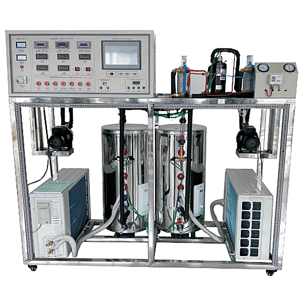
Heat pump technology is one of the effective measures to recover and utilize low-level heat energy. Researching and promoting heat pump technology is of great significance for energy conservation. With the development of refrigeration technology in recent years, heat pump technology has been increasingly widely used in China. The device can perform refrigeration cycle and heat pump demonstrations, and can observe the evaporation and condensation process of the refrigerant and the working phenomenon of the compressor.
This experimental system uses the heat balance method to measure the performance of the heat pump and refrigeration compressor. The system is m*nly composed of refrigeration compressor, evaporator, condenser, constant temperature water tank and electronic expansion valve. Sensors and detection instruments are used to collect state parameters such as temperature, pressure, flow, compressor power, current, frequency, etc. in the process of steam compression refrigeration cycle. The self-developed data acquisition board is connected to the computer. The measurement and control software with high real-time performance and humanized interface design developed based on object-oriented technology realizes real-time dynamic display of the thermal cycle process, performance parameter testing and calculation, and constitutes a heat pump-compressor performance experimental system with multi-functions such as detection, analysis, recording, testing, and drawing. Based on the basic unit, the following content is added: student design and innovative experiments.
2. M*n features
1. The compressor can be replaced;
2. The refrigerant (lubricant) can be replaced;
3. The pipeline can be cleaned;
4. The electronic expansion valve can realize self-programming control (verify various control algorithms)
; 5. The physical properties of different types of refrigerants can be placed in the database in the form of electronic spreadsheets for easy access; The experimental process and test conditions of the *r extraction and refrigerant filling device adopt a combination of manual and automatic control methods, using a DC variable frequency compressor, and can manually adjust the output frequency and the opening loop process of the electronic expansion valve. Animation demonstration.
3. Technical parameters:
1. Input power: single-phase three-wire ~ 220V ± 10% 50Hz
2. Working environment: temperature -10℃ ~ +40℃, relative humidity <85% (25℃), altitude <4000m
3. Device capacity: less than or equal to 5.kVA
4. Refrigerant: R134
5. Heating capacity : 4kW
6. Weight: 200kg
7. Dimensions (approximately): 180cm×70cm×164cm
8. Safety protection: with leakage voltage, leakage current overcurrent protection device, safety in line with national standards.
4. M*n configuration
1. The system unit is equipped with multiple protections such as high and low voltage protection system, overload protection, phase loss protection, defrosting function, etc. to ensure the safe, reliable and stable operation of the system without affecting the teaching course.
2. This experimental device adopts a heat exchanger forged with high-quality copper parts, which has high heat exchange efficiency, safety and reliability. The water tank adopts advanced brushed silver technology, combining fashion with top technology. The equipment has beautiful appearance. The inner tank is made of 304 st*nless steel, which is durable and not easy to corrode or damage.
3. The system adopts two sets of industrial *r source heat pump hot water units, which are consistent with the actual industrial equipment, so that teaching can be integrated with practical applications. The outdoor host adopts thickened sheet metal p*nt type, which can withstand different experimental environments and work effectively for a long time without rusting and corroding.
4. The whole set of tr*ning equipment integrates *r source heat pump heat engine system, electrical control system and fault simulation system. The process system is real and complete, with clear and compact structure, which fully meets the students' requirements for tr*ning.
5. The tr*ning device intuitively shows the system structure and working principle of the heat pump water heater. The structure of the heating cycle system and the real objects of the m*n components can be clearly seen. The system is also equipped with AC voltmeter, AC ammeter, temperature gauge and vacuum pressure gauge, so that the real-time working status of the entire heat pump system can be seen at a glance. 6. Equipment pipeline: The equipment moves the original refrigeration pipeline to the test bench
reasonably without changing its performance. It is also equipped with high and low pressure protectors and working fluid liquid visual mirrors. Different colors are used on the pipelines, with high-pressure pipes in red and low-pressure pipes in blue. 7. Refrigerant regulation flow control system: Flow control cold control system: It is specially used for throttling opening control in *r-conditioning systems. It can replace thermal expansion valves and capillaries, achieve good temperature and refrigerant flow control effects, and play a good energy-saving role. It can realize automatic adjustment of refrigerant flow to achieve rapid refrigeration, precise temperature control, energy saving and other purposes. It is reversible and can realize automatic flow control in refrigeration and refrigeration heat states. 1) Multi-point temperature detection: The controller simultaneously detects the system's refrigeration evaporator inlet temperature, heating evaporator inlet temperature and return *r pipe temperature. The detected temperature can be manually queried and displayed. When the sensor is damaged, the fault code is displayed. 2) Control object: 500P opening setting. 3) Control parameters can be set: All temperature parameters and time parameters related to control in the controller can be adjusted to adapt to different units or throttling devices. 4) Temperature and opening can be displayed and queried: All temperatures detected by the controller can be queried and the opening can also be queried and displayed in real time. 5) Manual adjustment function: During the development and commissioning stage of the unit, the opening of the expansion system flow can be manually adjusted through the controller to obt*n valid test data. In manual mode, press this key once to reduce the opening by one. Manual increase key In manual mode, press this key once to increase the opening by one. 6) Automatic refrigeration adjustment: During refrigeration operation, if the corresponding compressor is turned off, the current opening value rem*ns unchanged. After the compressor is started, the valve controller adjusts the opening every 60S, and the adjustment basis is △T (T return *r-T refrigeration) 7) Set query key: The temperature of the key point pipeline can be queried to facilitate the setting of the commissioning temperature. 8) Digital tube display: Display the flow opening, temperature and fault code online. 8. Condenser, shell and tube heat exchanger 2, cooling method: water cooling. 9. Evaporator; 2 st*nless steel plate evaporators
11. Flow meter; 2 electronic pot flow meters. 4020MA
12. Water pump, 2 st*nless steel water pumps
11.
One set of compressor frequency conversion control module 12. One set of temperature acquisition system, 16 channels, touch screen display, dynamic real-time data update, storage, curve display
13. Single chip microcomputer , PLC programmable design and control virtual simulation software:
This software is developed based on unity3d, with built-in experimental steps, experimental instructions, circuit diagram, component list, connection lines, power on, circuit diagram, scene reset, return and other buttons. After the connection and code are correct, the start/stop, forward motion and reverse motion buttons can be used to operate the 3D machine tool model movement. When the line is connected, the 3D machine tool model can be enlarged/reduced and translated.
1. Relay control: Read the experimental instructions and enter the experiment. By reading the circuit diagram, select relays, thermal relays, switches and other components in the component list and drag and drop them into the electrical cabinet. The limiter is placed on the three-dimensional machine tool model. You can choose to cover the cover. Some component names can be renamed. Then click the connect line button to connect the terminals. After the machine tool circuit is successfully connected, choose to turn on the power and operate. If the component or line connection is wrong, an error box will pop up. The scene can be reset at any time.
2. PLC control: The experiment is the same as relay control, and the PLC control function is added. After the connection is completed, enter the program writing interface through the PLC coding button. Write two forward and reverse programs. There are 12 ladder diagram symbols in total. After writing, select Submit for program verification. After successful verification, turn on the power to operate. If there are component, line connection, and code errors, an error box will pop up. The scene can be reset at any time.
3. Single chip microcomputer control: The experiment is the same as the relay control, with the single chip microcomputer control function added. After the connection is completed, enter the programming interface through the C coding button, enter the correct C language code, submit the verification successfully, and turn on the power to operate. Errors in components, line connections, and code errors will pop up an error box, and the scene can be reset at any time.
Experimental functions:
1. Refrigeration capacity and heating capacity experiments under standard working conditions
2. The impact of changes in parameters of each refrigeration system on refrigeration performance and heating energy efficiency ratio
3. Real-time update, storage, and curve display according to dynamics
4. Calculation of cooling capacity and heating capacity experiments
5. Simulation of the impact of changes in parameters of each refrigeration system on refrigeration performance and heating energy efficiency ratio
6. Automatic calculation of the m*n performance parameters of the system
7. Fixed frequency compressor performance test
8. Perform refrigeration cycle process and heat pump demonstration, and observe the evaporation and condensation process of the refrigerant and the working phenomenon of the compressor.
9. Variable frequency compressor performance test
10. Debugging of sub-expansion valve


 Wechat scan code follow us
