Shanghai Daiyu Education Equipment Manufacturing Co., Ltd.
Language:


| Serial number | Configuration Name | Specifications (length x width x height) | unit | quantity |
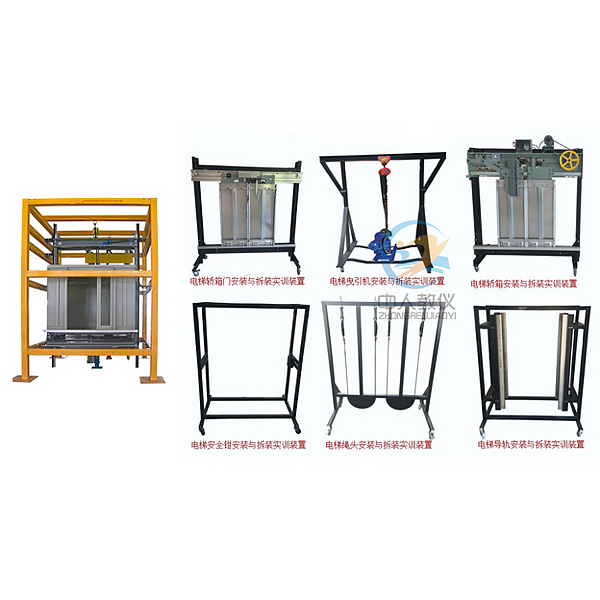
| 1 | Elevator guide r*l installation and adjustment tr*ning equipment |
Length: ≥1500mm Width: ≥1100mm Height: ≥1700mm |
set | 1 |
| 2 | Elevator rope head cone installation and adjustment tr*ning equipment |
Length: ≥1500mm Width: ≥1100mm Height: ≥1700mm |
set | 1 |
| 3 | Elevator traction machine installation and adjustment tr*ning equipment |
Length: ≥1500mm Width: ≥1100mm Height: ≥1700mm |
set | 1 |
| 4 | Elevator safety clamp installation and adjustment tr*ning equipment |
Length: ≥1500mm Width: ≥1100mm Height: ≥1700mm |
set | 1 |
| 5 | Elevator car door installation and adjustment tr*ning equipment |
Length: ≥1500mm Width: ≥1100mm Height: ≥1700mm |
set | 1 |
| 6 | Elevator hall door installation and adjustment tr*ning equipment |
Length: ≥1500mm Width: ≥1100mm Height: ≥1700mm |
set | 1 |
| 7 | Elevator car installation, disassembly and commissioning tr*ning equipment |
Can meet the requirements of elevator car installation, disassembly and commissioning assessment and tr*ning Length: ≥1500mmWidth : ≥1100mmHeight : ≥2400mm |
set | 1 |
| 8 | Elevator guide r*l verticality measuring instrument (optional) |
Measuring range: ≥0.5m/s Accuracy: ﹤±1% Number of saved measurements: ≥100 groups Power supply: AC 220V Maximum speed of driving motor : ≥3000rpm |
set | 1 |
| 9 | Elevator speed limiter tester (optional) |
Measuring range: ≥0.5m/s Accuracy: ﹤±1% Number of saved measurements: ≥100 groups Power supply: AC 220V Maximum speed of driving motor: ≥3000rpm |
set | 1 |
| 10 | Tr*ning tools | Common tools that can meet the needs of elevator installation, disassembly and debugging | set | 1 |
| 11 | Tr*ning guide | Installation, disassembly and debugging of physical elevator components | share | 1 |
| Serial number | name | quantity | unit | Remark |
| 1 | Hoistway frame | 1 | tower | Steel structure |
| 2 | Manual hoist | 2 | tower | |
| 3 | Wire and sinker | 1 | set | |
| 4 | Guide r*l bracket | 16 | set | |
| 5 | guide | 8 | strip | |
| 6 | Guide r*l connecting plate | 4 | piece | |
| 7 | Guide Shoes | 8 | set | |
| 8 | Lubricating oil bottle | 4 | set | |
| 9 | Car frame | 1 | indivual | Tie rod seat, inclined tie rod and shock absorbing rubber seat, etc. |
| 10 | Car | 1 | indivual | Car roof, car wall and car bottom components, etc. |
| 11 | Car door sill | 1 | strip | |
| 12 | Spring hydraulic buffer | 1 | indivual | |
| 13 | Door sill | 1 | strip | |
| 14 | Landing door sill bracket | 2 | indivual | |
| 15 | Counterweight frame | 1 | indivual | |
| 16 | Counterweight guardr*l | 1 | indivual | |
| 17 | Counterweight | 2 | piece | |
| 18 | Polyurethane buffer | 1 | indivual | |
| 19 | Mounting Accessories | 2 | set | 1 spare set |
| 20 | Installation and measuring tools | 1 | set | Level ruler, measuring tape, calibration ruler, magnet, etc. |
| twenty one | Random Information | 1 | share | Tr*ning guide and related atlas, etc. |
 Wechat scan code follow us

24-hour hotline+86 18916464525

Phone18916464525
ADD:Factory 414, District A, No. 6, Chongnan Road, Songjiang Science and Technology Park, Shanghai ICP: Sitemap