Shanghai Daiyu Education Equipment Manufacturing Co., Ltd.
Language:


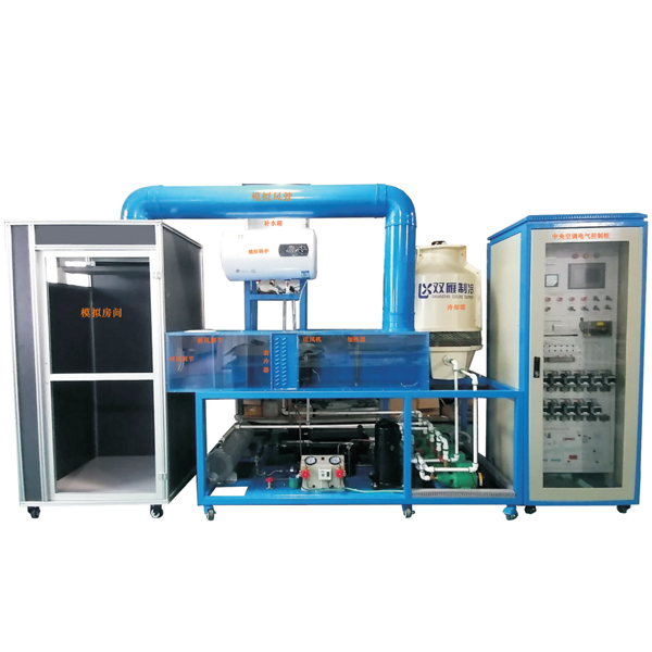


The ZRLR-13 central *r-conditioning unit is suitable for the teaching and practical tr*ning of courses such as "Refrigeration and Air- conditioning Machinery and Equipment", "Installation, Operation and M*ntenance of Refrigeration and Air-conditioning Devices", " Refrigeration and Air-conditioning Automation and Mechatronics ", and "Air Conditioning Technology and Application " in the majors of electromechanical equipment installation and m*ntenance, electromechanical technology application, electrical operation and control, electrical technology application, motors and electrical appliances , refrigeration and *r-conditioning equipment operation and m*ntenance in higher vocational colleges, secondary vocational schools and undergraduate colleges.
The central *r-conditioning system tr*ning platform is a comprehensive experimental device carefully designed based on the current domestic building electrical and building intelligence. This device combines the advanced technology in the current security field, starts from the requirements of teaching experiments, and fully realizes the working process of the central *r-conditioning full *r conditioning system with an engineering design concept.
Comprehensive; using the domestic advanced secondary return *r system, the same test bench can be used to complete different refrigeration system conditions
2. Features
1. Engineering: Most of the whole control system adopts the actual application components in industrial field.
Openness: The device adopts a transparent and open design, so students can clearly understand the working principle of the entire system
Safety protection: The device is equipped with a strong current leakage system
2. Strong practicability: The controller adopts a Mitsubishi PLC FX3U-48M and related relays, control switches, indicator lights, standard communication interface programmable controller, and the host computer software displays the system operation status and data in real time.
3. Strong intuitiveness: The tr*ning device intuitively displays the system structure and working principle of the central *r conditioner. The refrigeration cycle system structure and m*n components can be clearly seen. The system is also equipped with a complete system flow chart, AC voltmeter, AC ammeter, vacuum pressure gauge, and signal indicator lights to make the real-time working status of the entire system clear at a glance; it is convenient for teaching demonstrations and students to understand and grasp textbook knowledge. In addition, a sight glass is installed in the pipeline to observe the state of the refrigerant; the high-pressure pipeline is the red part, and the low-pressure pipeline is the blue part.
4. Strong comprehensiveness: The whole set of tr*ning equipment integrates refrigeration system, electrical control system and fault simulation system to meet the requirements of practical tr*ning.
5. Central *r conditioning cooling and heating circulation pipeline: connected with the latest color aluminum-plastic pipes and copper fittings, and marked with obvious direction signs. The pipeline is delivered to the simulated room or simulated *r duct through the solenoid valve and fan coil unit, and the wind speed switch or *r volume is adjusted according to the needs.
6. With computer serial interface, it forms an intelligent test device: the control software of the system adopts full Chinese menu operation. The temperature detector is a high-precision thermoelectric cooker, which is converted into digital signals by A/D analog-to-digital converter and output through RS232 computer interface. After the relevant program is installed on the computer, it can be clearly recorded and sampled on the screen and output through the printer for theoretical analysis.
7. Single chip microcomputer , PLC programmable design and control virtual simulation software:
This software is developed based on unity3d, and has built-in experimental steps, experimental instructions, circuit diagrams, component lists, connection lines, power on, circuit diagrams, scene reset, return and other buttons. After the connection and code are correct, the 3D machine tool model can be operated through the start/stop, forward motion, and reverse motion buttons . When the line is connected, the 3D machine tool model can be enlarged/reduced and translated.
1. Relay control: Read the experiment instruction manual and enter the experiment. By reading the circuit diagram, select relays, thermal relays, switches and other components in the component list and drag them to the electrical cabinet. Place the limiter on the 3D machine tool model. You can choose to cover the lid. Some component names can be renamed. Then click the connect line button to connect the terminals. After the machine tool circuit is successfully connected, choose to turn on the power and perform the operation. If the component or line connection is wrong, an error box will pop up and the scene can be reset at any time.
2.PLC control: The experiment is the same as the relay control, with the addition of the PLC control function. After the connection is completed, press the PLC coding button to enter the program writing interface, write two programs, forward and reverse, with a total of 12 ladder diagram symbols. After writing, select Submit for program verification. After successful verification, turn on the power to operate. Error boxes will pop up for components, line connections, and code errors, and the scene can be reset at any time.
3. Single-chip microcomputer control: The experiment is the same as relay control, with the addition of single-chip microcomputer control function. After the connection is completed, enter the programming interface through the C coding button, enter the correct C language code, submit and verify successfully, turn on the power to operate, and a prompt error box will pop up for component, line connection, and code errors, and the scene can be reset at any time.
3. Technical parameters
1. Power supply: three-phase five-wire AC 380 V±10% 50Hz;
2. Maximum cooling capacity: 7.5kW;
3. Maximum total input power: 6.5kW;
4. Refrigeration rated power: 7.5 kW;
5. Maximum stall current: 50A;
6. Heating rated power: 2.0kW;
7. Rated input current: 7A;
8. Circulating *r volume: 700m3/h;
9. Refrigerant: R22;
10. Leakage action current: ≤30mA;
11. Noise: 35-40dB (A);
12. Safety protection measures: It has four protection measures: overvoltage, overcurrent, overload, leakage and grounding, which meet the relevant national standards.
4. Device Configuration
1. Controller system configuration:
The control system consists of a programmable controller, data acquisition , force control configuration software, etc. The controller uses Mitsubishi PLC FX3U-48M programmable controller, and adds a 16-point pressure expansion module and two analog acquisition modules. The system has two control methods: manual and automatic, and the upper computer force control software can monitor the system operation conditions, that is, the cooling state, heating state, temperature, equipment operation state, etc. in the system. The temperature and other related system parameters are collected through the PLC analog module to control the entire system. The control process of the system can be changed by editing the PLC program. The configuration software, with the help of Windows 2000/XP multi-tasking environment, is the management and scheduling center of this system, realizing the centralized management of the entire system, as well as monitoring, scheduling, and management of the controlled equipment of the entire building, and realizing the linkage control of the equipment. When not connected to the object, it can also complete the central *r-conditioning electrical system troubleshooting tr*ning.
2. Control cabinet:
Iron double-layer matte dense pattern spray-coated structure, solid structure. The front door adopts transparent design, and the control components such as central controller, contactor, thermal protector can be observed. The panel has control switch knob, working status indicator light, system flow chart, PLC host unit and test points.
3. AC power control unit:
It is powered by a three-phase four-wire AC 380V power supply and is equipped with a leakage protector to control the total power supply of the control panel.
4. Simulate f*lure:
The simulated fault setting is completed in combination with the software. Students analyze the possible causes of the fault based on the process, determine the scope of the fault, and perform troubleshooting.
5. Measuring instruments
1) Power supply voltage indication unit: Provides 1 AC voltmeter and 1 AC ammeter to measure the system grid voltage and the working current of the compressor, cooling water pump, and refrigeration water pump. Refrigeration system pressure detection unit:
2) Provide 2 vacuum pressure gauges and 1 dual-group pressure controller, with measuring ranges of -0.1~1.5MPa and -0.1~3.5MPa respectively, which can display the pressure changes on the low-pressure side and high-pressure side of the system compressor and protect the compressor.
6. The device can realize two control modes: manual control and computer control:
A manual control buttons are on the door of the control cabinet. These control buttons are connected to the corresponding input variables of the PLC and can directly control the entire central *r conditioner;
B Computer control uses configuration technology to establish stable communication between the computer and PLC, thereby controlling the entire central *r conditioner and realizing various functions such as display and analysis of *r conditioner operation data. At the same time, it can also establish communication between the remote computer and the on-site computer through network upgrade to realize remote control of the central *r conditioner.
7. System schematic diagram:
In order to better understand the control and system principles of the central *r conditioner, a refrigeration system flow chart is drawn on the control panel, and corresponding working indicators of related components are provided. When the corresponding components are turned on or off, the corresponding status indicators light up or turn off.
8. Logos, fonts and flow charts are sprayed on the corresponding components on the control panel.
9. Control cabinet configuration table
|
serial number |
name |
unit |
quantity |
|
|
1 |
Power distribution control cabinet, network cabinet |
set |
1 |
1800*700*700MM, with blue frame structure and white as matching color, front and back doors, convenient for practical tr*ning, the front door is decorated with glass, beautiful and generous (panel: iron panel, laser engraving, color printing) |
|
2 |
Three-phase 4P with leakage switch |
Only |
32A |
|
|
3 |
Three-phase insurance |
tower |
1 |
32A |
|
4 |
450V ammeter, 30A ammeter |
indivual |
1 |
6L2 |
|
5 |
Button |
set |
8 |
|
|
6 |
Switching power supply: Provide power for the control system |
set |
1 |
Q60.: Provide +24V.+5V |
|
7 |
Intermediate relay |
set |
8 |
24V |
|
8 |
AC contactor |
set |
13 |
220V |
|
9 |
12-position terminal block |
set |
4 |
|
|
10 |
3-position terminal block |
Only |
14 |
|
|
11 |
7-inch color touch screen |
Only |
Kunlun News |
|
|
12 |
Communication line |
Only |
1 |
|
|
13 |
Hot water pump |
indivual |
1 |
|
|
14 |
Central *r conditioning control tr*ning software |
set |
1 |
|
|
15 |
Experimental operation instructions |
set |
1 |
|
|
16 |
PT100 sensor |
Only |
6 |
|
|
17 |
PLC, FX3U-48M |
tower |
1 |
|
|
18 |
Data acquisition system temperature acquisition module, FX2N-4AD-PT |
set |
2 |
|
|
19 |
Pressure acquisition module, FX2N-2AD |
piece |
1 |
|
|
20 |
Pressure transmitter, 0-10V |
Only |
2 |
|
|
twenty two |
Portable student terminal computer stand |
set |
1 |
(Steel-wood structure ≥ 500×550×900 mm) |
|
twenty three |
System flow chart |
set |
1 |
10. The central *r-conditioning tr*ning and assessment device uses a 3-HP water-cooling unit:
It provides cold source for the whole system, and uses a set of water distributors to distribute and adjust the cold capacity. The whole central *r conditioner uses PLC as the m*n control machine. The computer communicates with PLC through the communication line to control the operation of the whole *r conditioner. It can also be remotely controlled through the network. The operating parameters of the *r conditioner are collected by sensors and transmitters, and sent to PLC after conversion through A/D modules, and then sent to the computer by PLC for real-time display and monitoring.
11. Chiller Configuration Table
|
serial number |
name |
unit |
quantity |
|
|
1 |
Compressor (3P) |
tower |
1 |
Scroll compressor, under the same power, scroll compressor can provide a larger refrigeration compression ratio |
|
2 |
Evaporator, dry 3P |
Only |
1 |
304 st*nless steel, with 19MM st*nless steel tube as the evaporator, which overcomes the problem that the acid-base ratio of water in some areas is high and it is easy to damage the evaporator (copper is generally damaged in 3 years) |
|
3 |
Simulated boiler |
tower |
1 |
40L |
|
4 |
Liquid reservoir 2P |
indivual |
1 |
|
|
5 |
Water condenser |
set |
1 |
304 st*nless steel, with 19MM st*nless steel tube as the evaporator, which overcomes the problem that the acid-base ratio of water in some areas is high and it is easy to damage the evaporator (copper is generally damaged in 3 years) |
|
6 |
3T cooling water tower |
set |
1 |
|
|
7 |
Cooling fan |
indivual |
1 |
Axial flow FN suction type - 220/300MM |
|
8 |
Thermal Expansion Valve |
Only |
1 |
Danfoss Import |
|
9 |
||||
|
10 |
Hand valve |
Only |
4 |
Cont*ns: 1 filling valve, 1 stop valve, 2 high and low pressure sensor stop valves |
|
11 |
Angle valve |
2 |
2 refrigerant recovery valves |
|
|
12 |
High and low pressure gauge |
Only |
2 |
|
|
13 |
Cooling valve |
indivual |
4 |
Adopt brass lifting gate valve, structure: multi-turn handwheel type |
|
14 |
Cooling water pump |
Only |
2 |
One is used as the m*n pump and the other is used as a backup cooling water pump. When the m*n pump is damaged, the backup water pump can be started |
12. Chilled water system and refrigeration system:
The water system is the nerve terminal system of the central *r conditioner, providing refrigerant water and heat medium water for the end users. The system is equipped with 2 cooling water pumps (one of which is a standby), 2 refrigeration water pumps, and 1 hot water pump. A set of water distributors is used to distribute and adjust the cooling capacity. The entire central *r conditioner uses PLC as the m*n control machine. The computer communicates with the PLC through the communication line to control the operation of the entire *r conditioner. Remote control can also be achieved through the network. The operating parameters of the *r conditioner are collected by sensors and transmitters, and sent to the PLC after conversion through the A/D module, and then sent to the computer by the PLC for real-time display and monitoring.
Chiller and heating machine configuration table
|
serial number |
name |
unit |
quantity |
|
|
1 |
Trap |
set |
1 |
One inlet and four outlets: Made of 304 st*nless steel, with a dr*n port to dr*n the water in the device when it is not in use |
|
2 |
Water distributor valve |
indivual |
5 |
Adopt brass lifting gate valve, structure: multi-turn handwheel type |
|
2 |
Water collector |
set |
1 |
One inlet and four outlets: Made of 304 st*nless steel, with a dr*n port to dr*n the water in the device when it is not in use |
|
3 |
Water collector supporting valve |
indivual |
5 |
Adopt brass lifting gate valve, structure: multi-turn handwheel type |
|
2 |
St*nless steel water tank 400*300*350 |
set |
1 |
St*nless steel water tank 400*300*350 |
|
5 |
Refrigeration water pump |
Only |
2 |
One is used as the m*n pump and the other is used as a backup cooling water pump. When the m*n pump is damaged, the backup water pump can be started |
|
6 |
Refrigeration valves |
indivual |
5 |
Adopt brass lifting gate valve, structure: multi-turn handwheel type |
|
7 |
Refrigeration water pump |
Only |
2 |
One is used as the m*n pump and the other is used as a backup cooling water pump. When the m*n pump is damaged, the backup water pump can be started |
|
8 |
Heating valve |
indivual |
2 |
Adopt brass lifting gate valve, structure: multi-turn handwheel type |
|
9 |
Hot water pump |
Only |
1 |
|
|
10 |
Pipeline |
Adopt new aluminum-plastic pipe structure: the pipe is double-layer plastic with 0.1MM aluminum in the middle, durable and pressure-resistant, and can be folded and assembled repeatedly |
||
|
11 |
Brass connector |
Only |
80 |
The joints use 6-point brass joints, which can be disassembled and assembled repeatedly without damage. |
14. Central *r conditioning terminal system:
It consists of a simulation room and a combined wind cabinet. The simulation room adopts 30*30 industrial standard aluminum profile and double-sided p*nted wood structure, and is equipped with the same fan coil as the real *r conditioner terminal, with three-level speed regulation, which can be freely adjusted by the user by adjusting the switch. The combined wind cabinet system consists of return *r outlet, fresh *r mixing outlet, blower, central *r conditioner evaporator, pipeline, and solenoid valve.
Central *r conditioning terminal system meter
|
serial number |
name |
unit |
quantity |
|
|
1 |
Simulated guest room |
set |
1 |
2000*900*800, aluminum-wood structure with four wheels for easy movement, door made of plexiglass for improved practicality |
|
2 |
Room fan coil |
set |
1 |
F34 function: three-speed wind speed adjustment |
|
3 |
Wind speed adjustment switch |
Type 86 |
||
|
4 |
Return *r vent |
set |
1 |
|
|
5 |
Air mixing vents |
set |
1 |
With adjustment function |
|
6 |
Air supply duct |
set |
1 |
PVC |
|
7 |
Combined wind cabinet |
set |
Made of PV panels, it has good thermal insulation effect and will not condense. |
|
|
8 |
Blower |
indivual |
1 |
300MM, *r volume 2800/S |
|
9 |
Central *r conditioning professional cooling |
indivual |
1 |
20 square meters |
5. Tr*ning content
1. Practical tr*ning on the structure and equipment of central *r conditioners;
2. Practical tr*ning on starting and stopping central *r conditioning;
3. Central *r conditioning operation and adjustment tr*ning;
4. Conduct testing and tr*ning on the operating conditions and operating parameters of central *r conditioners;
5. Conduct advanced programming of programmable controllers (PLCs) and conduct practical tr*ning on installation, wiring and debugging of PLCs;
6. Equipped with pressure and temperature sensors and corresponding A/D conversion function modules, it can collect data and conduct real-time monitoring of the operation of the entire central *r conditioner;
7. Configuration technology application tr*ning: Use configuration technology to realize animation display of central *r-conditioning operation, operation data display, real-time monitoring, configuration and other functions;
8. Remote control tr*ning;
9. Network installation and setting tr*ning;
10. Tr*ning on installation and use of sensors and transmitters.
11.Touch screen tr*ning
12. Touch screen and PLC communication use
 Wechat scan code follow us

24-hour hotline+86 18916464525

Phone18916464525
ADD:Factory 414, District A, No. 6, Chongnan Road, Songjiang Science and Technology Park, Shanghai ICP: Sitemap