Shanghai Daiyu Education Equipment Manufacturing Co., Ltd.
Language:


| project | Basic theory and practical tr*ning teaching of professional courses |
| Function |
1. Understand the functions of each component of the reactor, understand the structure and characteristics of the reactor, and understand the working process of the reactor; 2. Master the basic operations and adjustment methods of the reactor, and understand the m*n factors that affect the reaction; 3. Master the reactor Common abnormal phenomena and treatment methods; 4. Master the production operations of ethyl acetate in reactors; 5. Be able to use equipment and instruments correctly, and perform timely m*ntenance and upkeep of equipment, instruments and instruments; 6. Learn to make preparations before driving ; 7. Drive normally and operate as required to adjust to the specified value; 8. Able to grasp the operating status of the equipment in a timely manner, discover, correctly judge, and handle various abnormal phenomena in a timely manner, and be able to perform emergency shutdown operations under special circumstances; be able to master modern information technology Management ability, use computers to collect and monitor on-site data; 9. Correctly fill in production records and analyze various data in a timely manner; 10. Park the vehicle normally; 11. Understand and master industrial site production safety knowledge. |
| Practical tr*ning function | Operational tr*ning content |
| Prepare to drive |
1. Reading and presentation of process flow diagrams. 2. Be familiar with the site numbers, functions, working principles and usage of on-site devices and m*n equipment, instruments and valves. Develop operation plans as required. Check whether all equipment, pipelines and valves in the process are in normal operating condition. Bring in utilities (water, electricity, oil) and ensure they are functioning properly. Power on the device and check whether the status of each instrument is normal; test run the equipment. |
| drive |
1. Start the machine according to the correct driving steps, and adjust the raw material flow, temperature, pressure, and stirring speed to the specified values. 2. Ability to perform heat exchanger switching operations. |
| normal operation |
Follow instructions to change operating parameters such as raw material flow, temperature, pressure, liquid level, and rotational speed to specified values and establish normal operation. Inspect various operating parameters such as flow, temperature, pressure, liquid level, and rotational speed as required and keep records, so as to determine whether each indicator is normal in a timely manner. Inspect the operating status of moving equipment (centrifugal pumps, metering pumps) as required, confirm and keep records. Observe the operating conditions of the reactor during normal operation and point out factors that may affect its normal operation. It can carry out feeding and discharging operations of intermittent reactions according to normal operation. It can perform heat exchange switching of jackets, coils, external coolers, etc. according to different requirements. It can switch between jackets and electric heating according to different requirements. |
| parking |
Follow normal parking procedures. Check the status of each equipment and valves after shutdown, and make records after confirmation. |
| Accident handling |
The operating conditions of the reactor can be understood through observation and analysis of operating parameters, and adjustments to the system can be made promptly when cert*n parameters are changed to ensure that the reaction proceeds normally. It can switch different control modes and restore the system to stable operation. Able to determine the cause of abnormal operation and take corresponding actions to restore the system to stable operation. |
| Equipment m*ntenance |
1. Starting, stopping, normal operation and d*ly m*ntenance of centrifugal pumps. 2. The structure, working principle, normal operation and m*ntenance of the heat exchanger. 3. The location, type, structure, working principle, normal operation and m*ntenance of the m*n valves (electric regulating valve, solenoid valve, pressure reducing valve, back pressure valve, dr*n valve). The measurement principles of various temperature, flow, pressure, and liquid level sensors ; the normal use of temperature, pressure, and liquid level display instruments and flow control instruments. The structure, principle, and operation methods of different types of mixers. |
| control instrument |
1. Measurement principles of temperature, flow and pressure sensors; normal use of temperature and pressure display instruments and flow control instruments. 2. Control the normal use of the execution device voltage regulator, electric regulating valve, and frequency converter. 3. Understand the parameters, detection locations, detection sensors and control methods that need to be detected and controlled when controlling the reactor. |
| software |
1. Familiarity, understanding and use of upper monitoring platform software 2. Mechanical tr*ning safety education virtual simulation software: This software is developed based on unity3d. The software adopts the form of three-dimensional roaming, and can control movement through the keyboard and the mouse to control the lens direction. It is equipped with mechanical Safety distance experiment, mechanical safety protection device experiment, and basic assessment of mechanical safety protection design. During the experiment, the three-dimensional roaming screen uses arrows and footprints to prompt moving to the experimental location. The circle around the mechanical object shows the working radius. The experimental process is accompanied by a three-dimensional robot. dialog box reminder. A. The content of the mechanical safety distance experiment includes the safety distance experiment to prevent upper and lower limbs from touching the danger zone (divided into two fence heights and opening sizes). After selecting to enter, GB23821-2009 "Mechanical Safety to Prevent Upper and Lower Limbs from Touching the Danger Zone" pops up in front of the camera. "Safe Distance" requirements, error demonstration: The experimental process is that after the human body enters the working radius of the mechanical object and is injured, the red screen and voice prompts that the human body has received mechanical damage, and returns to the original position and conducts the next experiment. The last step is the correct approach. B. Mechanical safety protection device experiments are divided into safety interlock switches, safety light curt*ns, safety mats, safety laser scanners and other protection device experiments. Optional categories (safety input, safety control, safety output, others), manufacturers, products List (safety interlock switch, safety light curt*n, safety mat, safety laser scanner, safety controller, safety relay, safety guardr*l). There is a blue flashing frame reminder at the installation location. Experimental process: select the safety guardr*l and install it, select the safety interlock switch (or select the safety light curt*n, safety mat, safety laser scanner) and install it, select the safety controller and install it in the electrical control box , select the safety relay and install it in the electrical control box, click the start button on the electrical control box. If you enter a dangerous area, the system will sound an alarm and the mechanical object will stop working. Select the reset button on the electrical control box to stop. C. The basic assessment of mechanical safety protection design requires the completion of the installation of the mechanical safety system, and the correct installation of safety guardr*ls, safety interlock switches, safety light curt*ns, safety mats, safety laser scanners, safety controllers, safety relays, 24V power supplies, signal lights and Emergency stop button, the assessment is divided into ten assessment points. Some assessment points have 3 options, which are freely chosen by the students. After selecting the final 10 assessment points, submit for confirmation, and the system will automatically obt*n the total score and the score of each assessment point. . D. The software must be on the same platform as a whole and cannot be displayed as separate resources. At the same time, the VR installation package of this software is provided to customers to facilitate users to expand into VR experiments. VR equipment and software installation and debugging are not required. |
| serial number | name | Device parameters | unit | quantity | Remark |
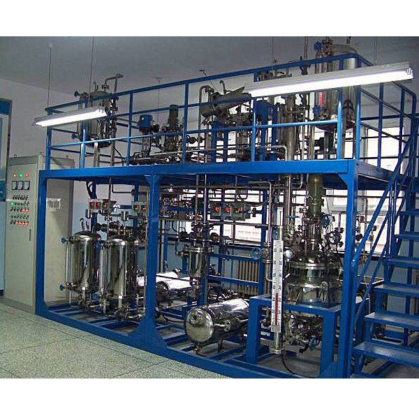
| 1 | Intermittent reactor unit operation tr*ning device |
1. Functions of the double-kettle reaction tr*ning device: 1. Understand the functions of each component of the reactor, understand the structure and characteristics of the reactor, and understand the working process of the reactor; 2. Master the basic operations and adjustment methods of the reactor, and understand the effects of the reaction The m*n influencing factors of Make good preparations before driving; 7. Drive normally and operate as required to adjust to the specified value; 8. Be able to grasp the operating status of the equipment in a timely manner, discover, correctly judge, and handle various abnormal phenomena in a timely manner, and be able to perform emergency shutdown operations in special circumstances ; Be able to master modern information technology management capabilities and use computers to collect and monitor on-site data; 9. Correctly fill in production records and analyze various data in a timely manner; 10. Park properly; 11. Understand and master industrial site production safety knowledge. 2. Double-kettle reaction tr*ning objects: 1. Frame\st*rs\guardr*l: frame length × width × height: about 4200 × 2000 × 3500mm, st*rcase width 700mm. Total equipment installation size: 4900×2000×3500mm. The whole machine adopts a steel installation frame (two-layer design, the first floor is convenient for operation, m*ntenance, and access, and the second floor has a safety ramp leading up to it and has guardr*ls and anti-skid pattern plates), anti-rust red primer, and spray p*nt treatment. The m*n frame of the upper and lower platforms uses 8# channel steel, the auxiliary frame uses 4# angle steel, and the four installation pillars use Φ89*3 steel pipes. The platform board uses δ3 lentil-shaped pattern board. The st*r frame has a total of 4# angle steel, and the st*r slab uses δ3 lentil-shaped pattern plate. The guardr*l vertical installation column uses 30×30×δ1.5 square steel pipe, and the horizontal pipe uses Φ25*δ1.5 steel pipe, 1 set; 2. Flange: matched with the corresponding equipment bracket, st*nless steel, 1 set; valve: matched with pipelines and equipment Matching, 1 set; pipeline: matching with equipment, including circulating cooling water branch pipe, material pipe, heat transfer oil pipe, condensate water pump inlet, etc., 1 set; 3. Raw material tank: φ377*600*2, st*nless steel, vertical, 2 sets ; 4.φ300*500*2, st*nless steel, vertical, 1 set; 5. High tank: φ377*550*2, st*nless steel, vertical, 2 sets; 6. Neutralization kettle product tank: φ300*800*2, 304 st*nless steel , horizontal type, 1 unit; 7. Reactor product tank: φ300*800*2, 304 st*nless steel, horizontal type, 1 unit; 8. Reactor steam condensate storage tank: φ219*300*2, 304 st*nless steel, horizontal type, 1 unit; 9. Thermal oil expansion tank: φ219*500*2, 304 st*nless steel, horizontal type, plus aluminum silicate insulation layer, 1 unit; 10. Thermal oil accident tank: φ377*600*2, 304 st*nless steel, horizontal type, 1 unit; 11. Cooling circulating water tank: 600*600*600, 304 st*nless steel, 1 set; 12. Neutralization kettle discharge cooler: φ141×550mm st*nless steel tube cooler (heat exchange area 0.5m2), 1 set; 13. Reaction kettle discharge Cooler: φ141×550mm st*nless steel tube cooler (heat exchange area 0.5m2), 1 unit; 14. Reactor steam vertical condenser: φ76×600mm st*nless steel tube heat exchanger (heat exchange area 0.3m2), 1 1 set; 15. Reactor steam horizontal condenser: φ159×1000mm st*nless steel tube heat exchanger (heat exchange area 1m2), 1 set; 16. Distillation reactor vertical fractionating column: φ76×550mm st*nless steel, the packing is φ6θ ring , with industrial liquid distributor, 1 set; 17. Neutralizing and stirring reactor: 50 liters of st*nless steel, height-to-diameter ratio 1:1.2, (pressure resistance 0.6Mpa, jacket heating mode: steam and electric heating thermal oil) method) with an aluminum silicate insulation layer, 1 set; 18. Distillation reactor: 50 liters of st*nless steel, with a height-to-diameter ratio of 1:2, (equipped with a vertical fractionating column, a vertical condenser, and a horizontal condenser, resistant to Pressure 0.6MPa, jacket heating method is steam and electric heating thermal oil) plus aluminum silicate insulation layer, 1 set; 19. Centrifugal pump: raw material pump, 380V, st*nless steel, 0~4.8m3/h, 2 units; 20. Condensate water pump, 380V, st*nless steel, 0~4.8m3/h, 2 units; 21. Micro plunger metering pump: 0-40L/H, st*nless steel, 1 unit; 22.4 grade motor : 380V, neutralization kettle Stirring motor, reactor stirring motor, 2 sets. 3. Double-kettle reaction tr*ning sensors: 1. Glass rotor flowmeter: LZB-15\25-250 liquid, high-level tank feed flow, 2 units; 2. LZB-6, 4-40L/H, raw material pump output flow , 1 set; 3. Flow meter: LZB-25\100-1000L/H liquid, distillation kettle liner condensation coil flow, 1 set; 4. Magnetic flap liquid level meter: DN20*720, with 4-20MA Remote transmission signal, neutralization stirring reactor liquid level measurement, 1 set; 5. Magnetic flap liquid level gauge: DN20*650, with 4-20MA remote transmission signal, distillation reactor liquid level measurement, 1 set; 6. Glass Pipe level gauge: DN20*600, flange type, 2 units; 7. Glass tube level gauge: DN20*450, flange type, 1 set; 8. Glass tube level gauge: DN20*550, flange type, 2 sets; 9. Glass tube level gauge: DN20*300, Flange type, 2 sets; 10. PT100 thermal resistance: M16*1.5 external wire interface, L=380, 4 sets; 11. Pointer pressure gauge: Y100, 0-0.6MPa, 2 sets; 12. Pressure transmitter: Diffused silicon pressure transmitter, 0~600kPa, 4~20mA signal output, DC24V power supply, 2 units; 13. Turbine flow meter: 0~1.2m3/h, 4~20mA output, 2 units; 14. Speed sensor: NPN Type Hall switch, DC24V power supply, pulse signal output, 2 pcs. 4. Double-kettle reaction tr*ning device actuator: 1. Frequency converter: Siemens frequency converter, three-phase 380V input, 0.75KW, 0~50Hz, 2 pieces; 2. Voltage regulating module: three-phase 380V, 35KW, with 4~ 20mA control signal input, 2 pcs. 5. Double-kettle reaction device instrumentation: 1. Intelligent flow totalizer: pulse signal input, 4~20mA/1~5V square root signal input, with RS485 communication interface, 2 units; 2. Intelligent inspection instrument: with Touch button, 6 channels, 1~5V signal input, with RS485 communication interface, 2 units; 3. Intelligent controller: intelligent adjustment controller, with touch button, universal signal input, with 4~20mA control signal output, with RS485 Communication interface, 4 units; 4. Flash alarm instrument: 8-channel flash alarm signal input, 1 unit. 6. Intelligent instrument electrical console and computer control console: Intelligent instrument electrical console: about 1650X700X1400 steel spray-p*nted piano-type structure on-site instrument electrical console (including instrument, embedded microcomputer position and switch position, and cont*ns DCS access port). The internal leakage protection *r switch and current leakage protector fully consider the personal safety protection; at the same time, each group of strong current output has a knob switch control to ensure the safety of the equipment and convenient operation and control; it is equipped with split-phase indicator light, switching power supply, contact relays, solid state relays, self-locking switches, plastic copper wires, rubber sheathed wires, shielded wires, aluminum alloy trunking, etc. 7. On-site intelligent instrument computer control system: Operator station upper monitoring computer: Brand computer: dual-core 3.0G, memory 4G, hard disk 1T, mouse, keyboard, 3-year warranty, monitor: 19" LCD, Windows operating system, National Alliance Guaranteed, 1 unit; communication network converter: RS485/232 communication converter, 1 unit. 8. Intelligent instrument upper monitoring software: MCGS industrial control configuration software: MCGS5.5 industrial control configuration software platform software, 1 set, upper monitoring software (With industrial control configuration software as the platform software) 1 set; supporting experimental instruction book, 1 set. |
set | 1 |
 Wechat scan code follow us

24-hour hotline+86 18916464525

Phone18916464525
ADD:Factory 414, District A, No. 6, Chongnan Road, Songjiang Science and Technology Park, Shanghai ICP: Sitemap