Shanghai Daiyu Education Equipment Manufacturing Co., Ltd.
Language:


| serial number | name | Technical Parameters | quantity | Remark |
| 1 | K series m*n controller module |
Input voltage: 21.6~26.4VDC hot-swappable: supported Module redundancy: master-slave hot standby redundancy, maximum redundant switching time 50ms CPU: industrial-grade PowerPC, 330MHz, 32-bit Memory: NOR FLASH, 16M Bytes NAND FLSAH, 128M Bytes DDR2 SDRAM, 128M Bytes power-down retention SRAM, 1M Bytes power-down protection: backup battery retention, data retention time after power f*lure is greater than 2 years, battery life is greater than 5 years, can be replaced online System Network: 100Mbps for dual network redundancy Ethernet control network: bus protocol PROFIBUS-DP, working mode dual network redundancy, communication rate 187.5 Kbps, 500Kbps, 1.5Mbps |
1 piece | |
| 2 | 4-slot m*n controller backplane module |
Power input: redundant input 3-channel power supply, 1 channel system power supply, 2-channel field power supply (1 channel 240W, 1 channel 120W) Power output: system power supply and field power supply both use 12 channels of output, and each two channels are redundantly controlled IP address setting: DIP switch setting IO-BUS station address setting: Jumper setting Power input: 24V±10% Number of slots: 4 Power input socket: 2-way redundant, 6-pin socket |
1 piece | |
| 3 | DC output power supply |
·Input voltage: 115VAC/230VAC, switch selection · Output voltage: 24VDC ·Protection: output short circuit, overload, overvoltage, over-temperature protection |
2 pieces | |
| 4 | System dedicated DC output power supply |
Input voltage: 176~264VAC Input current: 1.4A/230VAC Rated output voltage: 24VDC Output voltage accuracy: ±2% Rated output current: 10A Rated output power: 240W Voltage adjustment rate: ±1% Output overload protection: 105%-150 %, automatically recovers after the overload is eliminated. Output over-voltage protection: 125%-150% rated voltage. Output short-circuit protection: output short-circuit fault power supply protection, the power supply automatically recovers after the short-circuit fault is eliminated. |
2 pieces | |
| 5 | AC Power Distribution Board Module |
Input voltage: 110V/220VAC (2 channels) Output voltage: 110V/220VAC (each input corresponds to 5 outputs) |
1 piece | |
| 6 | DC power distribution board module |
Input voltage: 1 set of 2-channel 24VDC system power supply (Max. 240W); 1 set of 2-channel 24VDC (240W) field power supply, 1 set of 2-channel 24VDC (120W) field power supply, 1 set of 2-channel 24/48VDC auxiliary (query) power supply output voltage : Redundant system power supply (24VDC), 240W field power supply (24VDC), 120W field power supply; (24VDC) parallel distribution output on 2 6-hole connectors; redundant 24/48VDC auxiliary (query); load capacity: 24VDC, Maximum load 10A 48VDC, maximum load 5A |
1 piece | |
| 7 | Query the power distribution board module |
Output voltage: 24VDC/48VDC Output short-circuit protection: If a single output is short-circuited, the corresponding red indicator light will turn on Output current: 750mA/channel |
1 piece | |
| 8 | Bus type IO-BUS module |
Input voltage: 24VDC (-10%~+10%) Hot plug: supported Power supply mode and ports: 8 ports: 1~6 IO ports, 7 m*n control ports, 8 expansion ports Communication rate: 45.45k bps~3M bps Auto Adaptation Number of cascades: 3-level cascade/1.5Mbps, 2-level cascade/3Mbps (the delay between the output of each level HUB is not greater than 1.5μS) Transmission distance: 200m/1.5M bps (100m/3M bps) Electrical band load capacity detection: 30-node DP bus: detect open circuits of each branch DP bus and short circuit faults between bus differential lines |
2 pieces | |
| 9 | Bus type IO-BUS connector module |
Power input: 2-channel on-site power supply: 240W@24VDC, 120 W@24VDC Power output: The system power supply and on-site power supply both use 12-channel outputs, and each two channels are redundant. The on-site power supply 1 (240W) is divided into 8 channels. Power supply 2 (120W) is divided into 4 channels. Number of connector slots: 1 DP-HUB slot. Power input socket: 2 channels redundant, 6-pin socket, welded on the base plate. Composite bus connector: 2 sets of 8-port molex connections. Each connector has 6 channels, forming 6 p*rs of redundant links; each connector cont*ns one IO communication bus, one system 24V power supply, and one field 24V power supply. |
2 pieces | |
| 10 | 8-channel analog input module |
Number of channels: 8 Signal type: Current input Range: 4~20mA (maximum output range 0.5~22.7mA) Channel load capacity: Max. 800Ω@24VDC FS DAC resolution: 12 bits Accuracy: 0.20% FS (10~45℃ ) Stability: 0.05% FS non-linearity: 0.05% FS (-20~60℃) Isolation withstand voltage: 1500VAC, 1 minute @5mA |
1 piece | |
| 11 | 8-channel analog output module |
Number of channels: 8 Signal type: Current input Range: 4~20mA (maximum output range 0.5~22.7mA) Channel load capacity: Max. 800Ω@24VDC FS DAC resolution: 12 bits Accuracy: 0.20% FS (10~45℃ ) Stability: 0.05% FS non-linearity: 0.05% FS (-20~60℃) Isolation withstand voltage: 1500VAC, 1 minute @5mA |
1 piece | |
| 12 | Analog module base | K-AT01 | 2 pieces | |
| 13 | 16-channel 24VDC digital output module |
Number of channels: 16 Signal type: Source output Load capacity: Load current Max. 50mA@24VDC per channel; Load impedance: 700~3200Ω Isolation withstand voltage: 1500VAC, 1 minute @5mA Channel protection: Channel output current limiting fault diagnosis type : On-site power f*lure |
1 piece | |
| 14 | 16-channel DO base | K-DOT01 | 1 piece | |
| 15 | 16-channel DO relay output terminal board | K-DOR01 | 1 piece | |
| 16 | Engineer Station Software (Teaching Edition) | M*nly used for system management and configuration m*ntenance and modification. It has offline configuration test function; online download function; screen configuration and editing; function point configuration and definition function; control loop configuration function; alarm, trend chart and other definition and editing functions; communication definition and configuration function; device definition and configuration functions; database definition and configuration functions; report generation functions, etc. | 1 set | |
| 17 | Prefabricated cable | It is suitable for AC U0/U to be 300/500V for electric power, metallurgy, petrochemical and other industries, which are m*nly electronic computer-based automatic control systems, computer distributed control systems, automated control systems as control lines, and electronic computer cables for testing instruments. | 1 set |
| Analog input accuracy | ≤0.1% | |
| Analog output accuracy | ≤0.1% | |
| clock error | Error between on-site control stations | ≤0.1 seconds |
| Operator-to-station error | ≤0.1 seconds | |
| Recording accuracy | Analog time is accurate to seconds, switching time is accurate to milliseconds | |
| SOE resolution | Within the site ≤ 1 millisecond, between sites ≤ 2 milliseconds | |
| System av*lability | ≥99.99% | |
| Average system rep*r time | < 0.5 hours | |
| Network communication speed | 100Mbps | |
| operate | From input changes to display changes | ≤Collection period +1 second |
| Change from operational input to output | ≤1 second | |
| From input changes to output changes | ≤Acquisition cycle + Operation cycle | |
| screen display | Screen shows completion time | ≤1 second |
| Dynamic element update time | ≤1 second | |
| Scan cycle | Analog quantity | Fastest 50 milliseconds |
| Switch | Fastest 20 milliseconds | |
| control cycle | Loop control | Fastest 100 milliseconds |
| logic control | Fastest 50 milliseconds |
| system | Maximum number of dom*ns | 8 |
| single dom*n | Maximum number of stations | 62 |
| Engineering station | 1 | |
| operator station | ≤19 | |
| On-site control station (including communication station) | ≤40 | |
| Physical I/O points | ≤10000 pieces | |
| Number of control loops | ≤1000 pieces |
| serial number | Part Name | M*n configuration | quantity | Remark |
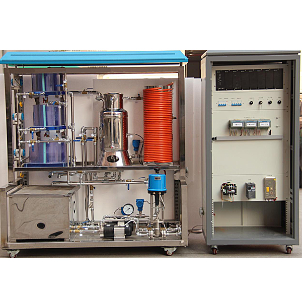
| 1 | Level water tank | It includes an upper water tank, a middle water tank, and a lower water tank. The three water tanks are all made of light blue high-quality organic glass, which is not only solid and durable, but also has high transparency, making it easy to directly observe changes in liquid level and record results. The dimensions of the upper and middle water tanks are: D=25cm, H=20cm; the dimensions of the lower water tank are: D=35cm, H=20cm. The water tank has a unique structure and consists of three tanks, namely the buffer tank, the working tank and the outlet tank. When the water enters, the water in the water pipe first flows into the buffer tank. When the water is discharged, the water in the working tank flows into the outlet tank through the partition with dovet*l groove. In this way, With buffering and linearization processing, the liquid level in the working tank is relatively stable and easy to observe. The bottom of the water tank is connected with a diffused silicon pressure sensor and transmitter, which can detect and transmit the pressure and liquid level of the water tank. The pressure transmitter adopts a two-wire analog pressure transmitter. The three water tanks can be combined into first-, second- and third-order single-loop liquid level control systems and double-closed-loop and triple-closed-loop liquid level cascade control systems. | 3 | |
| 2 | water tank | Made of 304 st*nless steel plate, the dimensions are: length × width × height = 68cm × 52cm × 43cm, with a capacity of 152L, which can fully meet the water supply needs of the experiment. There are two oval plastic filter covers inside the water tank to prevent debris from entering the water pump and pipes. The upper and lower parts of the water tank are equipped with water injection valves and dr*nage valves to facilitate the replacement of experimental water. | 1 | |
| 3 | boiler |
An atmospheric pressure boiler heated by a 3kW three-phase electric heating tube, including a heating layer (boiler liner) and a cooling layer (boiler jacket), both made of st*nless steel, m*nly completes relevant temperature experiments. When doing temperature experiments, the circulating water in the cooling layer can quickly dissipate the heat in the heating layer, causing the temperature of the heating layer to drop quickly. Both the cooling layer and the heating layer are equipped with temperature sensors to detect their temperatures, which can complete experiments such as fixed value control, cascade control, feedforward-feedback control, and decoupling control of temperature. Inner tank size: diameter Φ=185mm, height h=528mm, volume=14.2L; Boiler jacket size: diameter Φ=270mm, height h=420mm, volume=9.8L. |
1 | |
| 4 | Coil | Simulates the pipeline transportation and lag link in the industrial site. It is 35 meters long (43 turns) and 15mm in diameter. There are three different temperature detection points on the coil. Their lag time constants are different. During the experiment, different experiments can be performed. Need to choose | 1 set | |
| 5 | Pipes and valves |
Different temperature detection points. The outlet water from the coil can flow into the boiler liner through the switching of the manual valve, or it can flow back to the water storage tank through the turbine flowmeter. It can be used to complete temperature hysteresis and flow pure hysteresis control experiments. The entire system pipeline is connected by plastic-coated st*nless steel pipes. Φ20 pipes are used in front of the pump, Φ16 pipes are used behind the pump, and Φ25 pipes are used in the overflow pipe. All manual valves are made of high-quality ball valves, which completely avoids rust in the pipeline system. possibility. Effectively improve the service life of the experimental device. |
1 set | |
| 6 | Level Transmitter | Three diffused silicon liquid level transmitters are used to detect the liquid levels of three liquid level water tanks respectively; their measuring range is 0~5Kpa and the accuracy is 0.5. Material: full st*nless steel structure, aluminum alloy shell; range: 0~5KP; accuracy: 0.5%; insulation resistance: ≥20MΩ/50VDC; zero point temperature coefficient: ±0.5%FS/10℃; stability: ±0.5%FS/ 1 year; Output signal: 4~20mADC (two-wire system), with st*nless steel isolation diaphragm, and uses signal isolation technology to follow and compensate for sensor temperature drift. | 3 | |
| 7 | Temperature Sensor | Pt100 platinum thermal resistance temperature sensors are used to measure the water temperature of the boiler liner, boiler jacket, coil (with 3 test points) and the outlet of the upper water tank. Pt100 temperature measurement range: -200~+650℃. The Pt100 sensor has high accuracy and good thermal compensation, and can be used as a thermal resistor for standard calibration. Equipped with Pt100 thermal resistance standard signal conversion | 5 | |
| 8 | flow transmitter | A turbine flowmeter is used. The sensor part of the turbine flowmeter is a turbine structure. It is a speed detection instrument used to detect the size of water flow. When the flow rate is small, its accuracy will not be reduced. Nominal diameter: 10 mm (pipe thread G1/2″); Measuring range: 0~1.2m3/h; Accuracy: Level 1; Output signal: 4~20mA DC (two-wire system); Power supply: DC24V | 2 | |
| 9 | Electric regulating valve | An intelligent str*ght-stroke electric regulating valve is used to adjust the flow of the control loop. It has the advantages of high precision, advanced technology, small size, light weight, large driving force, strong function, integration of control unit and electric actuator , high reliability, easy operation, etc. The power supply is single-phase 220V, and the control signal is 4~20mADC. , can output a valve position signal of 4~20mADC, which is very convenient to use and calibrate. | 1 set | |
| 10 | Magnetic drive pump | This device uses a magnetic drive pump as the water supply system. The model is 16CQ-8P, the flow rate is 30 liters/min, the lift is 8 meters, the power is 0.18KW, and the rotation speed is 2800rpm. The pump body is entirely made of st*nless steel to prevent rust and have a long service life. This device uses two magnetic drive pumps, one is driven by three-phase 380V constant voltage, and the other is driven by three-phase frequency conversion 220V output. | 2 | |
| 11 | The electromagnetic valve | Installed in the bypass of the electric regulating valve, it plays the role of step interference. Solenoid valve working voltage: 220VAC; nominal diameter: DN15; pipe thread G1/2″ | 1 | |
| 12 | Three-phase electric heating tube | It is composed of three 1kW electric heating tubes connected in a star shape and is used to heat the water in the boiler liner. The resistance value of each heating tube is about 50Ω. | 1 set |
 Wechat scan code follow us

24-hour hotline+86 18916464525

Phone18916464525
ADD:Factory 414, District A, No. 6, Chongnan Road, Songjiang Science and Technology Park, Shanghai ICP: Sitemap