Shanghai Daiyu Education Equipment Manufacturing Co., Ltd.
Language:

PRODUCT

PRODUCT CENTER

DYQCF-6 gasoline engine disassembly and operation experimental device

Release time:2024-06-03 07:00viewed:times
  • DYQCF-6 gasoline engine disassembly and operation experimental device
1. Product Introduction
This teaching equipment consists of two parts: an electronically controlled gasoline engine assembly (easy to disassemble and assemble), a disassembly and assembly flip stand and an operation detection console. The disassembly and flipping bench provides tr*nees with practical tr*ning on engine disassembly and assembly. After the engine is assembled, it can be connected to the operation detection console to start and run the engine and detect the assembly effect of the engine.
two. Functional features
1. There is a color inkjet circuit diagram p*nted on the panel of the tr*ning platform . Students can visually compare the circuit diagram with the actual electronically controlled gasoline engine to understand and analyze the working principle of the control system;
2. The tr*ning platform consists of disassembly, assembly, flipping and operation testing. The console consists of two parts.
The disassembly and flipping bench consists of an electronically controlled gasoline engine assembly and an engine disassembly and assembly rack that can be flipped 360 degrees. The operation detection console consists of a control panel, engine electronic control unit, cooling system, fuel supply system, battery, etc.;
3 .The disassembly and assembly turning stand with reducer can be turned and stationary at any angle in the axial direction, and can be easily used for disassembly and assembly tr*ning. An oil pan is placed at the bottom to facilitate the collection of small parts, water and oil. Three, do not fall to the ground;
the operation detection console rack is equipped with all the components and elements for starting and running the engine, such as electronic control unit, water tank, fuel tank and oil pump, instruments, ignition switch, etc., and is used with the disassembly and assembly flip bench to conduct oil, circuit, water, The docking of the *r circuit can run the engine (acceleration/deceleration/idling conditions are normal) and test the effect of engine assembly;
4. There is a color UV flatbed printed circuit diagram on the tr*ning platform panel, and students can visually compare the circuit diagram with the actual engine to understand and analyze the working principle of the control system;
5. The panel is made of 4mm thick high-grade aluminum-plastic panels that are corrosion-resistant, impact-resistant, pollution-resistant, fire-proof, and moisture-proof. The surface is sprayed with primer through a special process; the panel is printed with colors that will never fade. System circuit diagram, the tr*ning bench panel is equipped with detection terminals, which can directly detect the electrical signals of each sensor , actuator, and engine control unit pin on the panel , such as resistance, voltage, current, frequency signal, etc.;
on the tr*ning bench panel It is equipped with automotive instruments, fuel pressure gauges, and vacuum pressure gauges, which can display changes in parameters such as engine speed, fuel injection pressure, and intake manifold pressure in real time;
6. The tr*ning platform is equipped with a diagnostic socket that can be connected to a dedicated or universal car decoder. It can perform self-diagnostic functions such as reading fault codes, clearing fault codes, and reading data streams for the engine electronic control system.
7. The tr*ning platform is equipped with installation protection devices such as a m*n power switch and a flywheel protective cover.
8. The base of the tr*ning platform is welded with a steel structure, and the surface is spray-coated. It is equipped with self-locking casters, making it flexible to move, safe, reliable, sturdy and durable.
9. Mechanical assembly and fitter assembly virtual simulation software: This software is developed based on unity3d, with optional 6-level image quality. It is equipped with the design and virtual disassembly and assembly of reducers and shafting structures, the design and simulation of common mechanical mechanisms , and a mechanism resource library. For a typical mechanical mechanism (virtual disassembly and assembly of a gasoline engine), the software is a whole software and cannot be individual resources.
A. Reducer design and virtual disassembly interface can choose worm gear bevel gear reducer, two-stage expanded cylindrical gear reducer, bevel cylindrical gear reducer, coaxial cylindrical gear reducer, bevel gear reducer, and one-stage cylindrical gear reducer. Gear reducer.
Worm bevel gear reducer: After entering the software, the assembly content is automatically played. Each step in the video has a text description
. Secondary expandable cylindrical gear reducer: After entering the software, the content is played in the form of a video. The video content should include: Part name ( Scan the QR code to see the names of parts), disassembly and assembly demonstration (including disassembly and assembly), virtual disassembly (including overall, low-speed shaft, medium-speed shaft, high-speed shaft, box cover, box seat)
conical cylindrical gear reducer, Coaxial cylindrical gear reducer, bevel gear reducer, first-level cylindrical gear reducer: click to enter and automatically jump to the edrawings interface. The models are all three-dimensional models. By clicking on the parts, the names of the parts are displayed, and the 360° view is av*lable Rotate, zoom in, zoom out, pan, and move parts to disassemble and assemble the entire reducer. At the same time, you can select the home button to return to the original state of the reducer. The bevel gear reducer and the first-stage cylindrical gear reducer have added the function of inserting a cross section, and the cross section can be freely dragged to observe the internal structure of the reducer.
B. Shaft structure design and virtual disassembly and assembly interface optional parts recognition, disassembly and assembly demonstration, and actual operation.
1. Parts recognition: three-dimensional model and part name including helical gear, non-hole end cover, coupling, coupling key, shaft, gear key, hole end cover, shaft sleeve, deep groove ball bearing, any All parts can be rotated 360°
2. Disassembly and assembly demonstration: There are 2 built-in cases. When you move the mouse to the position of a cert*n part (except the base and bearing seat), the part will automatically enlarge and the name of the part will be displayed. It is equipped with disassembly and Assembly button, the function is to automatically complete the disassembly and assembly of the shaft system structure by the software. All three-dimensional scenes can be rotated, enlarged, reduced and translated 360° in all directions.
3. Practical operation: The three-dimensional parts are neatly placed on the table. Students manually select the corresponding parts and move them to the shaft system structure. The parts can be installed only when they are placed in the correct order and in the correct position. There is a restart button to facilitate students to restart. Conduct virtual experiments. When you move the mouse to a cert*n part position (except the base and bearing seat), the part will automatically enlarge and the part name will be displayed.
C. Common mechanical mechanism design and simulation, optional hinge four-bar mechanism design and analysis, I\II type crank rocker mechanism design and analysis, offset crank slider mechanism design and analysis, crank swing guide rod mechanism design and analysis, hinge Four-bar mechanism with integrated trajectory, eccentric linear-acting roller push rod cam , and centering linear-acting flat-bottomed push rod cam.
1. Each mechanism should be able to input corresponding parameters, and the software can automatically calculate the parameters, and can perform motion simulation and automatically draw curves.
D. The mechanism resource library includes 11 types of planar link mechanisms, 5 types of cam mechanisms, 6 types of gear mechanisms, 8 types of transmission mechanisms, 11 types of tightening mechanisms, 6 types of gear tr*n mechanisms, and 8 types of other mechanisms (mechanical equipment simulation)
E , Virtual disassembly and assembly of gasoline engines, optional crankcase assembly and disassembly demonstration, crankcase virtual assembly, valve tr*n assembly and disassembly demonstration, valve tr*n virtual assembly
1. Both the crankcase assembly and disassembly demonstration and the gas distribution system assembly and disassembly demonstration are equipped with disassembly buttons, assembly buttons, restart, and disassembly observation buttons. When the mouse is moved to a cert*n part position, the part will automatically enlarge and the part name will be displayed. , the function is to automatically complete the disassembly and assembly of the shaft system structure by the software. When using the decomposition observation button, the 3D model of the crankcase or gas distribution system automatically displays an exploded view, which can be rotated, enlarged, reduced, and translated 360°.
2. The 3D parts of the crankcase virtual assembly and the gas distribution system virtual assembly are neatly arranged When placed on the desktop, students manually select the corresponding parts and move them to the mechanism. The parts can be installed only when they are placed in the correct order and in the correct position. There is a restart button to facilitate students to re-perform the virtual experiment. When you move the mouse to cert*n part locations, the part names are automatically displayed.
three. Technical specifications
Working power supply: DC 12V
Fuel label: According to engine model
Fuel tank volume: 10L
Working temperature: -40℃~+50℃
Color: 7032
steel pipe: 40*40*3mm
Panel cabinet: 1.5mm cold plate stamping and forming, set on the back for m*ntenance Door;
moving casters: 120*80mm
Appearance: 1500*1000*1700mm (length*width*height)
4. Basic configuration (per set)

serial number name Specifications and models unit quantity
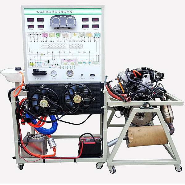
(1) 1 set of operation detection console
1 Test control panel Equipped with various detection terminals and color circuit diagram
(950*900*4mm aluminum-plastic plate)
set 1
2 Engine control computer (ECU) Original car set 1
3 instrument cluster Original car set 1
4 Diagnostic seat Original car indivual 1
5 Ignition switch assembly Original car indivual 1
6 fuel pressure gauge 0-10kg/cm2 indivual 1
7 Vacuum pressure gauge 0-76in.Hg indivual 1
8 Fuel tank 10L indivual 1
9 Gasoline pump (including gasoline pump plug) brand new set 1
10 Water tank and accessories Original car set 1
11 cooling electronic fan 12V, 80W indivual 2
12 battery 12V 65Ah tower 1
13 relay Including: starting relay, oil pump relay, cooling fan relay, etc. set 1
14 Butt harness   set 1
15 Fuse box   indivual 1
16 m*n power switch 50A indivual 1
17 Mobile stand (with self-locking casters, panel cabinet and base) 1000*700*1750mm
(length*width*height)
tower 1
18 Fault simulation and troubleshooting device   set 1
(2) 1 set of disassembly and assembly flip stand
1 Electronically controlled gasoline engine assembly Original car set 1
2 Intake and exhaust pipes Original car set 1
3 three way catalytic converter With new muffler set 1
4 Butt harness   set 1
5 Large area oil basin About 700×650×30mm (length×width×depth) indivual 1
6 Disassembly and assembly of flip stand (with self-locking caster device) Approximately 1300×600×800mm (length×width×height), with reducer, capable of flipping and stationary at any angle in the axial direction. set 1

DAIYUWechat scan code follow us

  • 24-hour hotline+86 18916464525

  • Phone18916464525

 ADD:Factory 414, District A, No. 6, Chongnan Road, Songjiang Science and Technology Park, Shanghai ICP: Sitemap