Shanghai Daiyu Education Equipment Manufacturing Co., Ltd.
Language:


| serial number | name | Specifications and models | unit | quantity |
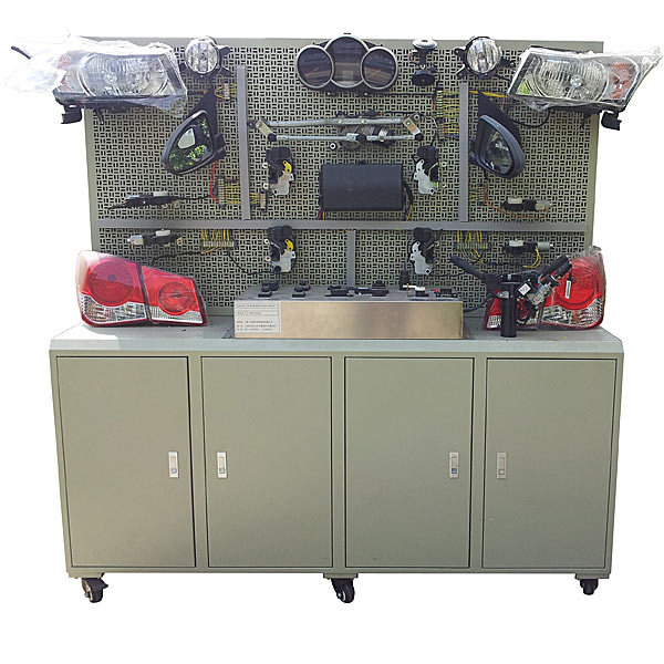
| 1 | panel | Equipped with various detection terminals and color circuit diagrams | set | 1 |
| 2 | Engine control computer (ECU) | Original car | set | 1 |
| 3 | Diagnostic seat | Original car | indivual | 1 |
| 4 | Ignition Switch | Original car | indivual | 1 |
| 5 | instrument cluster | Original car | set | 1 |
| 6 | Combination Switch | Original car | set | 1 |
| 7 | Left and right headlight assemblies | Original car | set | 1 |
| 8 | Left and right front fog lights | Original car | set | 1 |
| 9 | Left and right turn signals | Original car | set | 1 |
| 10 | Left and right turn side lights | Original car | set | 1 |
| 11 | Left and right combination t*l lights | Original car | set | 1 |
| 12 | License Plate Light | Original car | set | 1 |
| 13 | high mount brake light | Original car | indivual | 1 |
| 14 | light switch | Original car | set | 1 |
| 15 | brake light switch | Original car | set | 1 |
| 16 | Reversing light switch | Original car | set | 1 |
| 17 | hazard light switch | Original car | set | 1 |
| 18 | Wiring harness | set | 1 | |
| 19 | Wiper assembly | Original car | set | 1 |
| 20 | wiper controller | Original car | indivual | 1 |
| twenty one | Water jet motor | Original car | set | 1 |
| twenty two | watering bottle | Original car | set | 1 |
| twenty three | trumpet | Original car | indivual | 2 |
| twenty four | Horn relay | Original car | indivual | 1 |
| 25 | X contact relay | Original car | indivual | 1 |
| 26 | fog light relay | Original car | indivual | 1 |
| 27 | Distributorless ignition system | Includes igniter assembly, spark plug, crankshaft position sensor | set | 1 |
| 28 | Simulated injector indicator light | set | 1 | |
| 29 | fuel pump relay | Original car | indivual | 1 |
| 30 | fuel pump indicator light | Original car | indivual | 1 |
| 31 | Crankshaft position sensor and signal wheel | Original car | set | 1 |
| 32 | Electric window m*n switch | Original car | set | 1 |
| 33 | Left and right front door computers | Original car | indivual | 1 |
| 34 | Comfort computer | Original car | indivual | 1 |
| 35 | Right front door lock motor | Original car | set | 1 |
| 36 | Left and right rear power window motors | Original car | set | 1 |
| 37 | Left and right rear power window switches | Original car | set | 1 |
| 38 | Left and right rear door lock motors | Original car | set | 1 |
| 39 | car audio assembly | Original car | set | 1 |
| 40 | speaker | 6", 200W | right | 1 |
| 41 | Starter assembly | Original car | tower | 1 |
| 42 | Generator assembly | Original car | tower | 1 |
| 43 | Three-phase asynchronous motor | YT100L1-4 | tower | 1 |
| 44 | battery | 12V 45Ah | tower | 1 |
| 45 | Fuse box | indivual | 1 | |
| 46 | m*n power switch | 50A | indivual | 1 |
| 47 | Mobile stand (with self-locking casters) |
2000×700×1700mm (length×width×height) base with tool cabinet |
tower | 1 |
| 48 | Experimental patch cord | set | 1 | |
| 49 | Teacher's Manual | set | 1 | |
| 50 | Certificate and warranty card | set | 1 |
 Wechat scan code follow us

24-hour hotline+86 18916464525

Phone18916464525
ADD:Factory 414, District A, No. 6, Chongnan Road, Songjiang Science and Technology Park, Shanghai ICP: Sitemap