Shanghai Daiyu Education Equipment Manufacturing Co., Ltd.
Language:


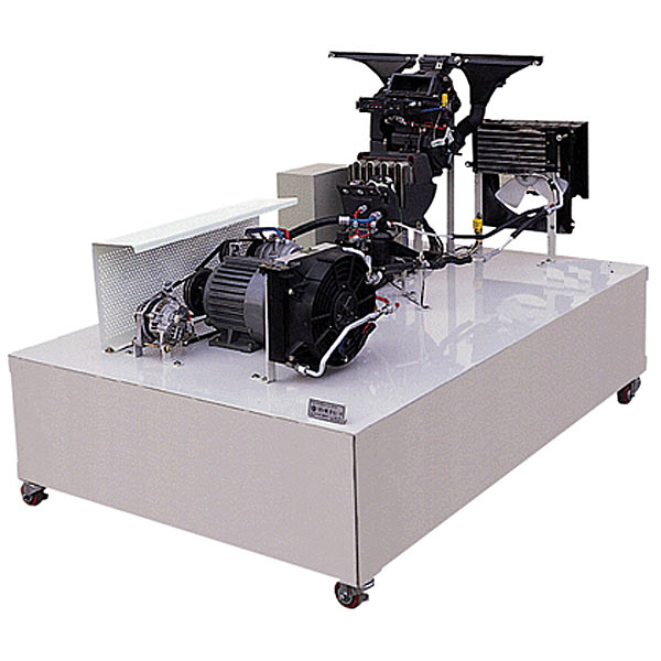


| serial number | name | Specifications and models | unit | quantity |
| 1 | Component icons and terminal labels | set | 1 | |
| 2 | Ignition Switch | indivual | 1 | |
| 3 | High pressure pressure gauge | R134a, 0~3.5MPa | indivual | 1 |
| 4 | low pressure pressure gauge | R134a, 0~1.5MPa | indivual | 1 |
| 5 | Digital *r inlet temperature gauge | indivual | 1 | |
| 6 | Digital *r outlet temperature gauge | indivual | 1 | |
| 7 | Air conditioning controller assembly | set | 1 | |
| 8 | Air conditioning evaporation box assembly | set | 1 | |
| 9 | Compressor assembly | set | 1 | |
| 10 | Expansion valve assembly | set | 1 | |
| 11 | dryer assembly | set | 1 | |
| 12 | Blower assembly | set | 1 | |
| 13 | condenser | indivual | 1 | |
| 14 | cooling electronic fan | set | 1 | |
| 15 | Three-phase asynchronous motor | YT 100L1-4/2.2KW | tower | 1 |
| 16 | Air inlet and outlet ducts and accessories | Original car brand new | set | 1 |
| 17 | Mobile stand (with self-locking casters) | 1300×1000×1300mm (length×width×height) | tower | 1 |
| 18 | Equipment Teacher's Manual | set | 1 | |
| 19 | Equipment Student Construction Manual | set | 1 | |
| 20 | Equipment certificate, warranty card | set | 1 |
 Wechat scan code follow us

24-hour hotline+86 18916464525

Phone18916464525
ADD:Factory 414, District A, No. 6, Chongnan Road, Songjiang Science and Technology Park, Shanghai ICP: Sitemap