Shanghai Daiyu Education Equipment Manufacturing Co., Ltd.
Language:


| serial number | name | Specifications and models | unit | quantity |
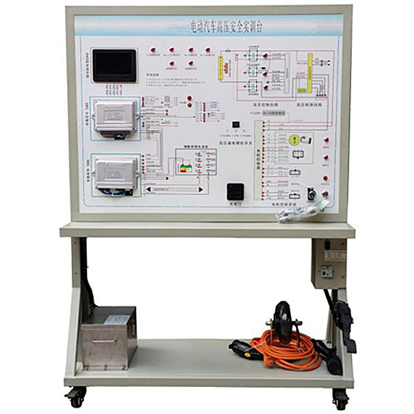
| 1 | Control panel and test bench |
1. Equipped with various detection terminals and color schematic diagrams 2. Cold plate stamping forming mobile stand: 1240*600*1700mm (length × width × height) 3. With 4 movable casters: |
set | 1 |
| 2 | Operating platform for electric vehicle motors, batteries and other components |
1. 40*40*3mm square tube welding bench: 1240*600*700mm (length × width × height) 2. With 4 movable casters: 3. Motor, battery and other components |
set | 1 |
| 3 | Electric vehicle lithium iron phosphate battery |
Lithium iron phosphate battery, with iron shell assembly and wiring; 72V with CAN-BUS communication and battery manager |
set | 1 |
| 4 | electric car motor |
1kW motor with Hall sensor Rated voltage: 72V Cooling method: *r cooling |
set | 1 |
| 5 | Electric vehicle brushless DC motor controller | Rated voltage: 72V | set | 1 |
| 6 | BMS-7 inch color screen monitor | With CAN-BUS communication | set | 1 |
| 7 | electronic accelerator pedal | Supporting | Only | 1 |
| 8 | Ignition Switch | Supporting | Only | 1 |
| 9 | brake switch | Supporting | Only | 1 |
| 10 | gear switch | Supporting | Only | 1 |
| 11 | car charger | 72V5A matching | tower | 1 |
| 12 | DC-DC converter | (72/12V) | set | 1 |
| 13 | Electric vehicle charging gun and socket | National standard for electric vehicles, CEBEA | set | 1 |
| 14 | battery management system |
With CAN-BUS communication; lithium iron phosphate battery terminal control ECU; lithium iron phosphate battery central control ECU; lithium iron phosphate battery display control ECU vehicle ECU; |
set | 1 |
| 15 | Electric vehicle high voltage safety system |
High-voltage control loop system (high-current total positive relay/m*n negative relay/pre-voltage relay, etc.); high-voltage detection loop system (insulation/current detection sensor); electric vehicle high-voltage safety control ECU (with CAN-BUS communication); |
set | 1 |
| 16 | Hall type current sensor | National standard products | set | 1 |
| 17 | Fault simulation and troubleshooting device | Supporting | set | 1 |
| 18 | Equipment Teacher's Manual | Supporting | set | 1 |
| 19 | Equipment certificate, warranty card | Supporting | set | 1 |
 Wechat scan code follow us

24-hour hotline+86 18916464525

Phone18916464525
ADD:Factory 414, District A, No. 6, Chongnan Road, Songjiang Science and Technology Park, Shanghai ICP: Sitemap