DYXNYC-22 high-pressure safety simulation measurement experimental device
Release time:2024-05-28 16:00viewed:times
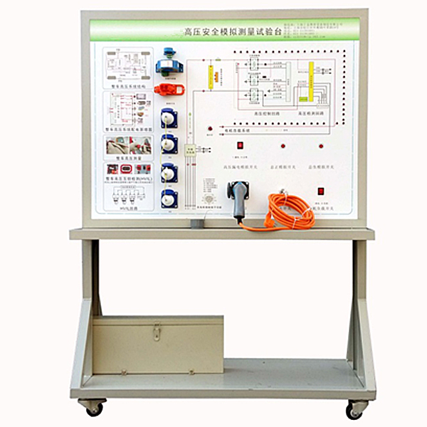
one. Product Introduction: Made
of new energy vehicle high-voltage safety system components, it demonstrates the structure and working principle of the new energy vehicle high-voltage safety system, and is suitable for the teaching needs of various colleges and universities for pure electric vehicle high-voltage safety system theory and m*ntenance tr*ning.
two. Equipment composition:
power battery pack, national standard charging gun and charging stand, leakage sensor module, insulation sensor module, safety m*ntenance plug module, leakage simulation operating unit, high-voltage safety system operating unit, operation console, tr*ning control button, principle panel and structural color Figure, movable stand.
three. Functional features
1. Use the combination of analog electricity and digital electricity to simulate the high-voltage power consumption area, high-voltage line transmission, low-voltage circuit protection of high-voltage circuits of pure electric vehicles and hybrid vehicles, as well as the areas where leakage may occur and the state of leakage. .
2. Use special leakage detection equipment to simulate the detection process.
3. The equipment panel is made of high-grade aluminum-plastic panels that are impact-resistant, pollution-resistant, fire-proof, and moisture-proof. The surface is sprayed with primer through a special process; the 4mm aluminum-plastic panel is printed with a UV flat color schematic diagram that will never fade; students can visually compare it. Use panel data and system objects to understand and analyze the components and principles of the system;
4. Simulate and measure the areas where leakage may occur and the state of leakage.
5. Mechanical assembly and fitter assembly virtual simulation software: This software is developed based on unity3d, with optional 6-level image quality. It is equipped with the design and virtual disassembly and assembly of reducers and shafting structures, the design and simulation of common mechanical mechanisms , and a mechanism resource library. For a typical mechanical mechanism (virtual disassembly and assembly of a gasoline engine), the software is a whole software and cannot be individual resources.
A. Reducer design and virtual disassembly interface can choose worm gear bevel gear reducer, two-stage expanded cylindrical gear reducer, bevel cylindrical gear reducer, coaxial cylindrical gear reducer, bevel gear reducer, and one-stage cylindrical gear reducer. Gear reducer.
Worm bevel gear reducer: After entering the software, the assembly content is automatically played. Each step in the video has a text description
. Secondary expandable cylindrical gear reducer: After entering the software, the content is played in the form of a video. The video content should include: Part name ( Scan the QR code to see the names of parts), disassembly and assembly demonstration (including disassembly and assembly), virtual disassembly (including overall, low-speed shaft, medium-speed shaft, high-speed shaft, box cover, box seat)
conical cylindrical gear reducer, Coaxial cylindrical gear reducer, bevel gear reducer, first-level cylindrical gear reducer: click to enter and automatically jump to the edrawings interface. The models are all three-dimensional models. By clicking on the parts, the names of the parts are displayed, and the 360° view is av*lable Rotate, zoom in, zoom out, pan, and move parts to disassemble and assemble the entire reducer. At the same time, you can select the home button to return to the original state of the reducer. The bevel gear reducer and the first-stage cylindrical gear reducer have added the function of inserting a cross section, and the cross section can be freely dragged to observe the internal structure of the reducer.
B. Shaft structure design and virtual disassembly and assembly interface optional parts recognition, disassembly and assembly demonstration, and actual operation.
1. Parts recognition: three-dimensional model and part name including helical gear, non-hole end cover, coupling, coupling key, shaft, gear key, hole end cover, shaft sleeve, deep groove ball bearing, any All parts can be rotated 360°
2. Disassembly and assembly demonstration: There are 2 built-in cases. When you move the mouse to the position of a cert*n part (except the base and bearing seat), the part will automatically enlarge and the name of the part will be displayed. It is equipped with disassembly and Assembly button, the function is to automatically complete the disassembly and assembly of the shaft system structure by the software. All three-dimensional scenes can be rotated, enlarged, reduced and translated 360° in all directions.
3. Practical operation: The three-dimensional parts are neatly placed on the table. Students manually select the corresponding parts and move them to the shaft system structure. The parts can be installed only when they are placed in the correct order and in the correct position. There is a restart button to facilitate students to restart. Conduct virtual experiments. When you move the mouse to a cert*n part location (except the base and bearing seat), the part will automatically enlarge and the part name will be displayed.
C. Common mechanical mechanism design and simulation, optional hinge four-bar mechanism design and analysis, I\II type crank rocker mechanism design and analysis, offset crank slider mechanism design and analysis, crank swing guide rod mechanism design and analysis, hinge Four-bar mechanism with integrated trajectory, eccentric linear-acting roller push rod cam , and centering linear-acting flat-bottomed push rod cam .
1. Each mechanism should be able to input corresponding parameters, and the software can automatically calculate the parameters, and can perform motion simulation and automatically draw curves.
D. The mechanism resource library includes 11 types of planar link mechanisms, 5 types of cam mechanisms, 6 types of gear mechanisms, 8 types of transmission mechanisms, 11 types of tightening mechanisms, 6 types of gear tr*n mechanisms, and 8 types of other mechanisms (mechanical equipment simulation)
E , virtual disassembly and assembly of gasoline engines, optional crankcase assembly and disassembly demonstration, crankcase virtual assembly, valve tr*n assembly and disassembly demonstration, valve tr*n virtual assembly
1, crankcase assembly and disassembly demonstration and valve tr*n assembly and disassembly demonstration both have disassembly button, assembly button, restart, and decomposition observation button. When the mouse is moved to a cert*n part position, the part will automatically enlarge and the part name will be displayed. The software automatically completes the disassembly and assembly of the shaft system structure. When using the decomposition observation button, the 3D model of the crankcase or gas distribution system automatically displays an exploded view, which can be rotated, enlarged, reduced, and translated 360°.
2. The 3D parts of the crankcase virtual assembly and the gas distribution system virtual assembly are neatly arranged When placed on the desktop, students manually select the corresponding parts and move them to the mechanism. The parts can be installed only when they are placed in the correct order and in the correct position. There is a restart button to facilitate students to re-perform the virtual experiment. When you move the mouse to cert*n part locations, the part names are automatically displayed.
4. Technical specifications
1. External power supply: AC 220V±10% 50Hz
2. Working voltage: DC 12V
3. Working temperature: -40℃~+50℃
4. Overall dimensions: 1240×600×1700mm (length×width×height) )
5. Practical tr*ning and experimental projects
1. Cognition of high-voltage safety systems of new energy vehicles.
2. Practical tr*ning on basic control principles and working process verification of new energy vehicle high-voltage safety systems.
3. Basic control principle and working process verification tr*ning of high-voltage interlocking for new energy vehicle high-voltage lines.
4. Cognitive tr*ning on high-voltage areas of new energy vehicles.
5. Practical tr*ning on simulating and measuring the areas where leakage may occur and the status of leakage.
6. New energy vehicle high-voltage safety system measurement and m*ntenance experience tr*ning.


 Wechat scan code follow us
