DYXNYC-14 Electric Drive Transmission System Training Device
Release time:2024-05-28 08:30viewed:times
The product introduction
uses domestic m*nstream new energy pure electric vehicle components. The functions and control methods are exactly the same as those of general pure electric vehicles. It truly presents the connection control relationship, installation position and operating parameters between the core components of the new energy electric drive system. As well as safety precautions for high-voltage systems, it cultivates students' ability to analyze and deal with faults in new energy electric drive systems, and is suitable for teaching new energy drive transmission courses and rep*ring tr*ning equipment in various colleges and universities.
Functional features
1. Real and operable new energy electric drive transmission system integration, fully demonstrating the composition structure and logical control relationship of each m*n component.
2. Each m*n component is installed on the platform, and the electrical connection method is the same as that of the actual vehicle, which can be easily disassembled, allowing students to master the key points of disassembly and assembly of system components and safety protection during the disassembly, assembly and wiring process;
3. Magnetic powder is installed at the output end of the transmission shaft. The brake simulates the vehicle load system. By adjusting the load size at both ends, it can truly reproduce the changes in parameters such as current and voltage under different working conditions of the electric drive transmission system (starting, acceleration, constant speed, deceleration, parking, climbing, etc.).
4. The power battery pack is equipped with a mechanical m*ntenance switch. After pulling out the mechanical m*ntenance switch, you can open the upper cover for observation; high-voltage electrical connectors are all national standard products with reliable performance.
5. The power battery pack has a translucent design and built-in LED row lights to facilitate students to observe the internal structure of the battery.
6. Real mechanical gear transmission and braking system, observe the changes of braking energy feedback current, and master the concept of braking energy recovery.
7. The equipment is equipped with an electric vacuum-assisted hydraulic braking system, and the switch signal intelligently controls the vacuum pump operation through the pressure sensor
. 8. The equipment is equipped with a 12V power ground mechanical switch, which can disconnect the 12V ground at any time and cut off the power supply of the entire system.
9. The tr*ning platform is equipped with safety protection devices such as brake guards.
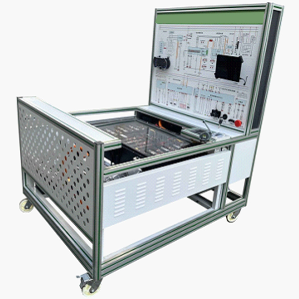
10. The UV flatbed printing panel completely displays the working principle diagram of the electric drive transmission system, and is equipped with detection terminals. With the help of a multimeter and oscilloscope, parameter changes under various states can be detected in real time.
11. The equipment consists of a movable platform and a panel. The platform is placed horizontally and the m*n components are installed. 4 casters are installed at the bottom of the equipment for flexible movement. At the same time, the casters have self-locking devices to fix the position.
12. There is a tabletop on the base directly in front of the equipment testing panel, which is convenient for placing materials, testing instruments, etc.
13. The equipment is equipped with an intelligent fault setting and assessment system. The teacher sets the fault, and the students analyze and find the fault point. Each m*n component leads to the detection port, and the fault location is directly detected to master the actual vehicle fault handling ability.
14. Mechanical assembly and fitter assembly virtual simulation software: This software is developed based on unity3d, with optional 6-level image quality. It is equipped with the design and virtual disassembly and assembly of reducers and shafting structures, the design and simulation of common mechanical mechanisms , and a mechanism resource library. For a typical mechanical mechanism (virtual disassembly and assembly of a gasoline engine), the software is a whole software and cannot be individual resources.
A. Reducer design and virtual disassembly interface can choose worm gear bevel gear reducer, two-stage expanded cylindrical gear reducer, bevel cylindrical gear reducer, coaxial cylindrical gear reducer, bevel gear reducer, and one-stage cylindrical gear reducer. Gear reducer.
Worm bevel gear reducer: After entering the software, the assembly content is automatically played. Each step in the video has a text description
. Secondary expandable cylindrical gear reducer: After entering the software, the content is played in the form of a video. The video content should include: Part name ( Scan the QR code to see the names of parts), disassembly and assembly demonstration (including disassembly and assembly), virtual disassembly (including overall, low-speed shaft, medium-speed shaft, high-speed shaft, box cover, box seat)
conical cylindrical gear reducer, Coaxial cylindrical gear reducer, bevel gear reducer, first-level cylindrical gear reducer: click to enter and automatically jump to the edrawings interface. The models are all three-dimensional models. By clicking on the parts, the names of the parts are displayed, and the 360° view is av*lable Rotate, zoom in, zoom out, pan, and move parts to disassemble and assemble the entire reducer. At the same time, you can select the home button to return to the original state of the reducer. The bevel gear reducer and the first-stage cylindrical gear reducer have added the function of inserting a cross section, and the cross section can be freely dragged to observe the internal structure of the reducer.
B. Shaft structure design and virtual disassembly and assembly interface optional parts recognition, disassembly and assembly demonstration, and actual operation.
1. Parts recognition: three-dimensional model and part name including helical gear, non-hole end cover, coupling, coupling key, shaft, gear key, hole end cover, shaft sleeve, deep groove ball bearing, any All parts can be rotated 360°
2. Disassembly and assembly demonstration: There are 2 built-in cases. When you move the mouse to the position of a cert*n part (except the base and bearing seat), the part will automatically enlarge and the name of the part will be displayed. It is equipped with disassembly and Assembly button, the function is to automatically complete the disassembly and assembly of the shaft system structure by the software. All three-dimensional scenes can be rotated, enlarged, reduced and translated 360° in all directions.
3. Practical operation: The three-dimensional parts are neatly placed on the table. Students manually select the corresponding parts and move them to the shaft system structure. The parts can be installed only when they are placed in the correct order and in the correct position. There is a restart button to facilitate students to restart. Conduct virtual experiments. When you move the mouse to a cert*n part location (except the base and bearing seat), the part will automatically enlarge and the part name will be displayed.
C. Common mechanical mechanism design and simulation, optional hinge four-bar mechanism design and analysis, I\II type crank rocker mechanism design and analysis, offset crank slider mechanism design and analysis, crank swing guide rod mechanism design and analysis, hinge Four-bar mechanism with integrated trajectory, eccentric linear-acting roller push rod cam , and centering linear-acting flat-bottomed push rod cam .
1. Each mechanism should be able to input corresponding parameters, and the software can automatically calculate the parameters, and can perform motion simulation and automatically draw curves.
D. The mechanism resource library includes 11 types of planar link mechanisms, 5 types of cam mechanisms, 6 types of gear mechanisms, 8 types of transmission mechanisms, 11 types of tightening mechanisms, 6 types of gear tr*n mechanisms, and 8 types of other mechanisms (mechanical equipment simulation).
E. For virtual disassembly and assembly of gasoline engines, you can choose from crankcase assembly and disassembly demonstration, crankcase virtual assembly, valve tr*n assembly and disassembly demonstration, valve tr*n virtual assembly
1, crankcase assembly and disassembly demonstration and valve tr*n assembly and disassembly demonstration. Disassembly button, assembly button, restart, and decomposition observation button. When the mouse is moved to a cert*n part position, the part will automatically enlarge and the part name will be displayed. The software automatically completes the disassembly and assembly of the shaft system structure. When using the decomposition observation button, the 3D model of the crankcase or gas distribution system automatically displays an exploded view, which can be rotated, enlarged, reduced, and translated 360°.
2. The 3D parts of the crankcase virtual assembly and the gas distribution system virtual assembly are neatly arranged When placed on the desktop, students manually select the corresponding parts and move them to the mechanism. The parts can be installed only when they are placed in the correct order and in the correct position. There is a restart button to facilitate students to re-perform the virtual experiment. When you move the mouse to cert*n part locations, the part names are automatically displayed.
Technical specifications
1. Dimensions (mm): 1600*1000*1700 (length*width*height)
2. Input power supply: AC220V±10% 50Hz
3. Auxiliary battery: 12V45AH
4. Power battery type: environmentally friendly lithium iron phosphate power Battery (square aluminum shell, single cell 3.2V50AH)
Power battery pack capacity: 72V50AH
Full charge and discharge times: 2000 times
Working temperature: -20°~60°
5. Motor controller: 72V300A (intelligent AC frequency conversion control technology)
6. Drive motor: 72V5KW (AC variable frequency asynchronous motor)
7. Gearbox: two-stage helical gear transmission, total reduction ratio 1:10; operating noise is less than 70 decibels
8. Magnetic powder brake: PBS-50 (with adjustable tension controller)
rated Torque: 50N.m
Allowable speed: 1500r/min
Practical tr*ning project
1. Cognition of the control principles of new energy electric drive transmission systems.
2. Functional understanding of the m*n components of the new energy electric drive transmission system.
3. Practical tr*ning experiments on the logical control relationships of new energy electric drive transmission systems under various states, and mastering the changing rules of parameters such as current, voltage, motor speed, and load.
4. How the electronic accelerator pedal controls the speed of the drive motor.
5. The impact of load changes on the speed of the drive motor.
6. Safety precautions for operating new energy high-voltage systems, and high-voltage connector plugging and unplugging methods.
7. Fault analysis and diagnosis of new energy electric drive transmission system.
Basic configuration:
lithium iron phosphate power battery pack, vehicle charger, DC-DC converter, instrument, national standard charging socket and charging gun, motor controller, electronic throttle assembly, shift mechanism assembly, drive motor, gearbox, transmission Axle, front wheel disc brake, belt drive, magnetic powder brake, manual tension controller, booster belt pump assembly, vacuum pump assembly, vacuum tank assembly, auxiliary battery, intelligent fault setting and assessment system, movable bench ( Principle panel with installation detection terminals).


 Wechat scan code follow us
