Shanghai Daiyu Education Equipment Manufacturing Co., Ltd.
Language:


| serial number | name | Specifications and models | unit | quantity |
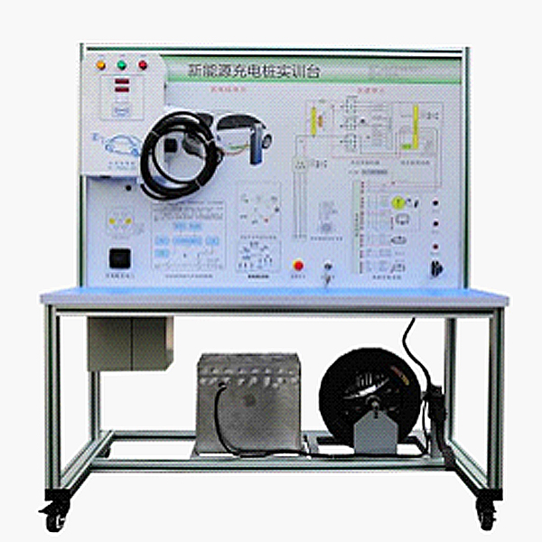
| 1 | Test control panel | Equipped with various detection terminals, color circuit diagram and working principle diagram, 1200*900mm | set | 1 |
| 2 | Charging pile components | National standard 220V16A, 3.5KW | set | 1 |
| 3 | Charging socket and charging gun | National standard | set | 1 |
| 4 | Smart charging card, recharge software | Supporting | set | 1 |
| 5 | Electric vehicle motor | 48V1KW | set | 1 |
| 6 | Electric vehicle motor controller | 48V1KW | set | 1 |
| 7 | Accelerator pedal, brake pedal, power battery pack | Supporting | set | 1 |
| 8 | Analog indicator light | Supporting | set | 1 |
| 9 | Operation switch | Supporting | set | 1 |
| 10 | DC contactor | Supporting | set | 1 |
| 11 | Mobile stand | 1240×600×1700mm (with self-locking casters) | tower | 1 |
| 12 | Fault simulation and troubleshooting device | Supporting | set | 1 |
| 13 | Fuse box | Supporting | set | 1 |
| 14 | Warranty card/certificate | Supporting | set | 1 |
| 15 | Teacher's Manual | Supporting | set | 1 |
 Wechat scan code follow us

24-hour hotline+86 18916464525

Phone18916464525
ADD:Factory 414, District A, No. 6, Chongnan Road, Songjiang Science and Technology Park, Shanghai ICP: Sitemap