DYXNYQD-12 New Energy Vehicle permanent magnet synchronous motor performance detection experimental device
Release time:2024-05-26 02:30viewed:times
1. Product introduction:
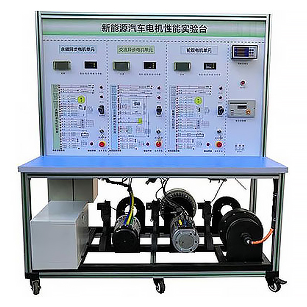
It is made of real components of pure electric vehicle drive motor and control system (60V2.2KW permanent magnet synchronous motor) to demonstrate the structure and working principle of new energy vehicle drive motor and control system. It is equipped with a motor performance detection system (digital display voltage Ammeter, tachometer, torque meter, power meter, magnetic powder brake, test host computer software) to achieve the m*n performance data test of the motor. It is suitable for the disassembly, assembly and m*ntenance, structure and principle cognition, system operation, dynamic demonstration of functions, fault detection and diagnosis, and m*n performance data testing of motors in various colleges and universities for theoretical and m*ntenance tr*ning of drive motors and control systems.
2. Product functions
1. Install the real components of the pure electric vehicle drive motor and control system, including charger and charging socket, drive motor, ignition switch, motor controller, gear switch, accelerator pedal, power switch, DC-DC module, Instruments, relays, batteries and other modules, real operational pure electric vehicle drive motors and control systems, display the structure and principles of the system, and dynamically demonstrate the working process of the system.
2. Achieve understanding of the structure and principles of the drive motor and control system of pure electric vehicles, experience the relationship between the driver's intention and the operation of the motor, and complete various performance tests of the drive motor and control system.
3. Equipped with a motor performance testing system (digital voltage and ammeter, tachometer, torque meter, power meter, magnetic powder brake, test host computer software) to test the m*n performance data of the motor. The motor test host computer software can display the change curves of motor torque, speed, and power over a period of time, and can visually display the changes of these parameters during the motor acceleration and deceleration process.
4. The panel is made of 4mm thick aluminum-plastic plate, and the vertically installed panel is UV flatbed inkjet printed with a color complete standard system drawing board; students can visually compare the drawing board and the actual object to understand and analyze the working principle of the system.
5. There are detection terminals installed on the panel, which can directly detect the electrical signals of system circuit components on the panel, such as resistance, voltage, current, frequency signals, etc.
6. The multi-functional instrument truly displays system current and voltage, speed, gear and other data changes.
7. The motor controller has a diagnostic interface, and the system data flow information (including brake switch, gear position, motor speed, voltage and current, electronic throttle, etc. working status) and fault content can be read through the host computer software. 8. The installation of a fault simulation system can realize fault setting and diagnosis and elimination of low-voltage circuit systems. It can set up 12 common fault settings and assess fault points.
9. The equipment frame is constructed of two integrated all-aluminum alloy profiles, 40mm×40mm and 40mm×80mm, which are oil-resistant, corrosion-resistant and easy to clean. The table is 40CM wide and paved with 32mm thick colored high-density composite boards, which is durable and rust-free. , with 4 swivel casters with self-locking devices for easy movement.
10. Supporting teaching materials such as practical tr*ning (experiment) instructions, including working principles, practical tr*ning projects, fault settings and analysis and other key points.
11. Install safety protection devices: emergency stop switch, mechanical m*n power switch, m*ntenance switch, protective cover for rotating parts, high-voltage safety protection devices and warning prompts.
3. Technical specifications
1. Overall dimensions (mm): 1500×700×1700 (length×width×height)
2. Panel dimensions (mm): 1448×940mm (length*width)
3. Mobile casters: 100*60mm
4 .Operating temperature: -40℃~+50℃
5. Drive motor and controller: DC60V2.2KW 3000rpm (permanent magnet synchronous motor)
6. Battery: lithium iron phosphate power battery pack 60V20AH with charger
7. Motor performance detection system :
HCN-101 torque sensor : Torque range: 0-±20Nm, accuracy: ±0.5%, speed range: 0-6000 rpm, power supply: ±15VDC, torque signal: 5~15kHz, speed signal: 60 pulses/rev , working temperature: -20-60℃, overload capacity: 150%, line length: 5 meters;
HN-201 torque speed power meter (torque meter): power supply: 220VAC communication: RS485, external supply: ±15V;
M400 data collection Software: Includes data acquisition software and RS485 to USB data cable;
Magnetic powder brake: PBS-20 (with DC24V4A adjustable tension controller)
SX-96B digital display: digital display displays current, voltage, frequency, power, and rotational speed values;
8 . Mechanical assembly and fitter assembly virtual simulation software: This software is developed based on unity3d, with optional 6-level image quality. It is equipped with the design and virtual disassembly and assembly of reducers and shafting structures, common mechanical mechanism design and simulation, mechanism resource library, typical Mechanical mechanism (virtual disassembly and assembly of gasoline engines), the software is a whole software and cannot be individual resources.
A. Reducer design and virtual disassembly interface can choose worm gear bevel gear reducer, two-stage expanded cylindrical gear reducer, bevel cylindrical gear reducer, coaxial cylindrical gear reducer, bevel gear reducer, and one-stage cylindrical gear reducer. Gear reducer.
Worm bevel gear reducer: After entering the software, the assembly content is automatically played. Each step in the video has a text description
. Secondary expandable cylindrical gear reducer: After entering the software, the content is played in the form of a video. The video content should include: Part name ( Scan the QR code to see the names of parts), disassembly and assembly demonstration (including disassembly and assembly), virtual disassembly (including overall, low-speed shaft, medium-speed shaft, high-speed shaft, box cover, box seat)
conical cylindrical gear reducer, Coaxial cylindrical gear reducer, bevel gear reducer, first-level cylindrical gear reducer: click to enter and automatically jump to the edrawings interface. The models are all three-dimensional models., by clicking on the component to display the component name, you can rotate, enlarge, reduce and pan 360°. At the same time, you can disassemble and assemble the entire reducer through the move component function. At the same time, you can select the home button to return to the reducer** *Initial state. The bevel gear reducer and first-stage cylindrical gear reducer have added the function of inserting a cross section, and the cross section can be freely dragged to observe the internal structure of the reducer.
B. Shaft structure design and virtual disassembly and assembly interface optional parts recognition, disassembly and assembly demonstration, and actual operation.
1. Parts recognition: three-dimensional model and part name including helical gear, non-hole end cover, coupling, coupling key, shaft, gear key, hole end cover, shaft sleeve, deep groove ball bearing, any All parts can be rotated 360°
2. Disassembly and assembly demonstration: There are 2 built-in cases. When you move the mouse to the position of a cert*n part (except the base and bearing seat), the part will automatically enlarge and the name of the part will be displayed. It is equipped with disassembly and Assembly button, the function is to automatically complete the disassembly and assembly of the shaft system structure by the software. All three-dimensional scenes can be rotated, enlarged, reduced and translated 360° in all directions.
3. Practical operation: The three-dimensional parts are neatly placed on the table. Students manually select the corresponding parts and move them to the shaft system structure. The parts can be installed only when they are placed in the correct order and in the correct position. There is a restart button to facilitate students to restart. Conduct virtual experiments. When you move the mouse to a cert*n part position (except the base and bearing seat), the part will automatically enlarge and the part name will be displayed.
C. Common mechanical mechanism design and simulation, optional hinge four-bar mechanism design and analysis, I\II type crank rocker mechanism design and analysis, offset crank slider mechanism design and analysis, crank swing guide rod mechanism design and analysis, hinge Four-bar mechanism with integrated trajectory, eccentric linear-acting roller push rod cam , and centering linear-acting flat-bottomed push rod cam .
1. Each mechanism should be able to input corresponding parameters, and the software can automatically calculate the parameters, and can perform motion simulation and automatically draw curves.
D. The mechanism resource library includes 11 types of planar link mechanisms, 5 types of cam mechanisms, 6 types of gear mechanisms, 8 types of transmission mechanisms, 11 types of tightening mechanisms, 6 types of gear tr*n mechanisms, and 8 types of other mechanisms (mechanical equipment simulation)
E , virtual disassembly and assembly of gasoline engines, optional crankcase assembly and disassembly demonstration, crankcase virtual assembly, valve tr*n assembly and disassembly demonstration, valve tr*n virtual assembly
1, crankcase assembly and disassembly demonstration and valve tr*n assembly and disassembly demonstration both have disassembly button, assembly button, restart, and decomposition observation button. When the mouse is moved to a cert*n part position, the part will automatically enlarge and the part name will be displayed. The software automatically completes the disassembly and assembly of the shaft system structure. When the decomposition observation button is used, the 3D model of the crankcase or gas distribution system automatically displays an exploded view, which can be rotated, enlarged, reduced, and translated 360°.
2. The 3D parts of the crankcase virtual assembly and the gas distribution system virtual assembly are neatly arranged When placed on the desktop, students manually select the corresponding parts and move them to the mechanism. The parts can be installed only when they are placed in the correct order and in the correct position. There is a restart button to facilitate students to re-perform the virtual experiment. When you move the mouse to cert*n part locations, the part names are automatically displayed.
4. Practical tr*ning (experimental) projects
1. Drive motor and control system m*ntenance and operation methods;
2. Drive motor fault diagnosis and rep*r;
3. Motor control system fault diagnosis and rep*r;
4. Motor performance and energy management detection ;
5. The role of the manual m*ntenance switch in the strong current circuit;
6. The protective role of high-voltage interlock;
7. The working principle and pin definition of the vehicle charger, common faults and replacement of the vehicle charger, and battery charging operation;
8. DC- Working principle and pin definition of DC converter, common faults and replacement methods of DC-DC conversion;
9. Composition and function of motor system components, control principle of drive motor and control system;
10. Measurement method of control parameters of drive motor and control system;
11. Common faults and troubleshooting methods of the drive motor and control system;
12. Working principle and pin definitions of the electronic accelerator pedal, common faults and replacement methods of the electronic accelerator pedal;
13. Working principle and pin definitions of the gear controller (switch), Common faults and replacement methods of gear controller (switch);
14. Motor performance testing experimental tr*ning (voltage, current, speed, torque, power test).
15. The changing relationship of motor speed, voltage, current, torque, power and other parameters when the motor is operating at a constant speed of the vehicle
. 16. The relationship between the changes in motor speed, voltage, current, torque, power and other parameters when the motor is accelerating the vehicle.
17. The relationship between the changes of motor speed, voltage, current, torque, power and other parameters when the motor is decelerating the vehicle.
18. F*lure analysis and troubleshooting when the motor does not rotate.
5. Basic configuration
detection control panel (equipped with various detection terminals, 1448×940mm color circuit diagram and working principle diagram), instruments, ignition switch, motor controller, vehicle charger and charging interface, DC-DC converter, lithium power Battery pack, electric vehicle motor (permanent magnet synchronous motor), brake switch, gear switch, throttle control device, high current relay, m*n power switch, emergency stop switch, auxiliary battery (12V45AH), motor performance detection system (digital display voltage Ammeter, tachometer, torque meter, power meter, magnetic powder brake, test host computer software), motor and torque sensor and magnetic powder brake connector, SX-96B digital display meter, integrated all-aluminum alloy profile mobile bench (1500 ×700×1700mm with self-locking caster device, principle panel with installation detection terminals, panel 1448×940mm), fault assessment system, equipment operating instructions.


 Wechat scan code follow us
