DYXNYDC-01 Electric Vehicle Battery Demolition Experimental Device
Release time:2024-05-24 17:30viewed:times
1. Product Introduction:
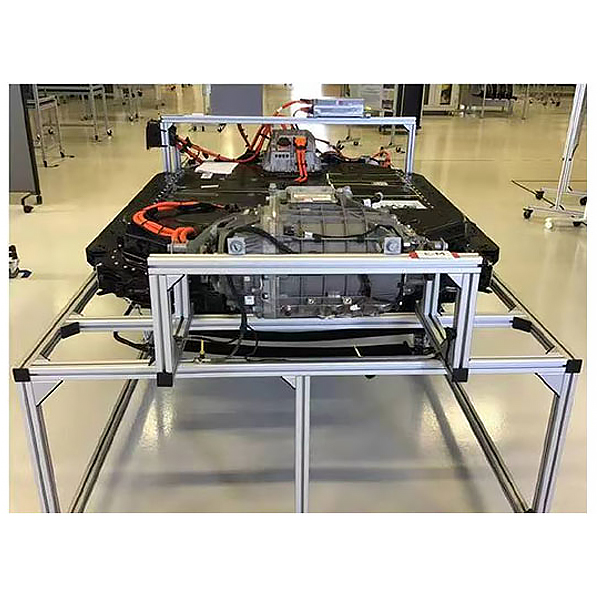
The original pure electric vehicle power battery pack is selected (renovated), including the physical production of its battery management system (BMS), which truly presents the connection control relationship, installation position and operation between the core components of the iron lithium power battery pack. parameters, and safety precautions for high-voltage systems; by comparing the circuit schematics, students assemble and connect the wiring themselves, cultivating their hands-on battery assembly and connection skills, which is suitable for pure electric vehicle power battery pack assemblies (including battery pack assemblies and battery management systems) , battery temperature sensor , Hall current sensor, DC contactor) decomposition and assembly, single cell voltage and internal resistance detection tr*ning operations.
2. Functional features
1. The tr*ning platform is equipped with a pure electric vehicle power battery pack assembly, including its battery management system (BMS).
2. The battery pack device is fully functional and clearly displays each single battery and their grouping and wiring methods, and the battery module can be disassembled and assembled repeatedly.
3. The battery pack should be arranged on the tr*ning platform according to the original vehicle layout, and must meet the requirements of making it convenient for students to repeatedly disassemble and install the battery module.
4. The installation position of the BMS on the power battery pack and the electrical and mechanical connection method must be consistent with the original vehicle to meet the requirements of tr*nees to repeatedly disassemble and install the BMS.
5. The tr*ning platform is equipped with a single battery charger , which can recharge the single battery.
6. Students can conduct actual measurements on single cell voltage and internal resistance.
7. It is equipped with teaching materials such as practical tr*ning guides, which fully describe the working principles, practical tr*ning projects, fault settings and analysis and other key points.
8. The equipment frame is constructed of two integrated all-aluminum alloy profiles, 40mm × 40mm and 40mm × 80mm. It is oil-resistant, corrosion-resistant, easy to clean, durable and rust-free. It is equipped with universal casters for easy movement and a locking mechanism .
9. The equipment consists of a movable platform (with a schematic teaching board), which is placed horizontally, and the m*n components are installed; 4 universal casters with self-locking devices are installed at the bottom.
10. Mechanical assembly and fitter assembly virtual simulation software: This software is developed based on unity3d, with optional 6-level image quality. It is equipped with the design and virtual disassembly and assembly of reducers and shafting structures, the design and simulation of common mechanical mechanisms, and a mechanism resource library. For a typical mechanical mechanism (virtual disassembly and assembly of a gasoline engine), the software is a whole software and cannot be individual resources.
A. Reducer design and virtual disassembly interface can choose worm gear bevel gear reducer, two-stage expanded cylindrical gear reducer, bevel cylindrical gear reducer, coaxial cylindrical gear reducer, bevel gear reducer, and one-stage cylindrical gear reducer. Gear reducer.
Worm bevel gear reducer: After entering the software, the assembly content is automatically played. Each step in the video has a text description
. Secondary expandable cylindrical gear reducer: After entering the software, the content is played in the form of a video. The video content should include: Part name ( Scan the QR code to see the names of parts), disassembly and assembly demonstration (including disassembly and assembly), virtual disassembly (including overall, low-speed shaft, medium-speed shaft, high-speed shaft, box cover, box seat)
conical cylindrical gear reducer, Coaxial cylindrical gear reducer, bevel gear reducer, first-level cylindrical gear reducer: click to enter and automatically jump to the edrawings interface. The models are all three-dimensional models . By clicking on the parts, the names of the parts are displayed, and the 360° view is av*lable Rotate, enlarge, reduce, translate, and at the same time, the entire reducer can be disassembled and assembled through the moving parts function. At the same time, you can select the home button to return to the original state of the reducer. The bevel gear reducer and the first-stage cylindrical gear reducer have added the function of inserting a cross section, and the cross section can be freely dragged to observe the internal structure of the reducer.
B. Shaft structure design and virtual disassembly and assembly interface optional parts recognition, disassembly and assembly demonstration, and actual operation.
1. Parts recognition: three-dimensional model and part name including helical gear, non-hole end cover, coupling, coupling key, shaft, gear key, hole end cover, shaft sleeve, deep groove ball bearing, any All parts can be rotated 360°
2. Disassembly and assembly demonstration: There are 2 built-in cases. When you move the mouse to the position of a cert*n part (except the base and bearing seat), the part will automatically enlarge and the name of the part will be displayed. It is equipped with disassembly and Assembly button, the function is to automatically complete the disassembly and assembly of the shaft system structure by the software. All three-dimensional scenes can be rotated, enlarged, reduced and translated 360° in all directions.
3. Practical operation: The three-dimensional parts are neatly placed on the table. Students manually select the corresponding parts and move them to the shaft system structure. The parts can be installed only when they are placed in the correct order and in the correct position. There is a restart button to facilitate students to restart. Conduct virtual experiments. When you move the mouse to a cert*n part position (except the base and bearing seat), the part will automatically enlarge and the part name will be displayed.
C. Common mechanical mechanism design and simulation, optional hinge four-bar mechanism design and analysis, I\II type crank rocker mechanism design and analysis, offset crank slider mechanism design and analysis, crank swing guide rod mechanism design and analysis, hinge Four-bar mechanism with integrated trajectory, eccentric linear-acting roller push rod cam , and centering linear-acting flat-bottomed push rod cam .
1. Each mechanism should be able to input corresponding parameters, and the software can automatically calculate the parameters, and can perform motion simulation and automatically draw curves.
D. The mechanism resource library includes 11 types of planar link mechanisms, 5 types of cam mechanisms, 6 types of gear mechanisms, 8 types of transmission mechanisms, 11 types of tightening mechanisms, 6 types of gear tr*n mechanisms, and 8 types of other mechanisms (mechanical equipment simulation)
E , virtual disassembly and assembly of gasoline engines, optional crankcase assembly and disassembly demonstration, crankcase virtual assembly, valve tr*n assembly and disassembly demonstration, valve tr*n virtual assembly
1. Crankcase assembly and disassembly demonstration and valve tr*n assembly and disassembly demonstration both have disassembly button, assembly button, restart, and decomposition observation button. When the mouse is moved to a cert*n part position, the part will automatically enlarge and the part name will be displayed. The software automatically completes the disassembly and assembly of the shaft system structure. When the decomposition observation button is used, the three-dimensional model of the crankcase or gas distribution system automatically displays an exploded view, which can be rotated, enlarged, reduced, and translated 360°.
2. The three-dimensional parts of the crankcase virtual assembly and the gas distribution system virtual assembly are neatly placed on the desktop. Students manually select the corresponding parts and move them to the mechanism. The parts can be installed only when they are placed in the correct order and in the correct position. There is a restart button to facilitate students to re-run virtual experiments. When you move the mouse to cert*n part locations, the part names are automatically displayed.
3. Technical specifications
1. Power battery type: original car
2. Single battery specifications: original car
3. Power battery voltage and capacity: original car
4. Single battery charging external power supply: AC 220V±10% 50Hz ( charging condition )
5. Working temperature: -10℃~+50℃
IV. Practical tr*ning items
1. Students assemble battery packs and BMS by hand, and understand the control principles of new energy power battery packs (BMS).
2. Students assemble the battery pack and BMS by hand, and understand the functions of the m*n components of the new energy power battery pack (BMS).
3. Single battery charge and discharge experiment.
4. Single battery internal resistance test experiment.
5. Practical tr*ning on disassembly and assembly of battery packs for pure electric vehicles.
5. Basic configuration:
power battery pack and BMS assembly, emergency power-off switch, m*ntenance switch, Hall current sensor, DC contactor (including charging relay, total positive relay, total negative relay, precharge relay), single battery charging machine, an integrated mobile stand made of all-aluminum alloy profiles (2500×14000×1300mm with self-locking casters), and equipment operating instructions.


 Wechat scan code follow us
