Dyxnycdz-03 New Energy Vehicle AC Charging Pile Experimental Device
Release time:2024-05-24 14:30viewed:times
1. Product introduction : Made with real components
of new energy vehicle AC charging devices and vehicle charging systems, it can demonstrate the structure and working principle of charging piles and vehicle charging systems, and is suitable for various colleges and universities to conduct theoretical and m*ntenance studies on charging piles and vehicle charging systems. Tr*ning needs for disassembly, assembly and m*ntenance, structure and principle understanding, system operation, dynamic demonstration of functions, fault detection and diagnosis.
2. Functional features
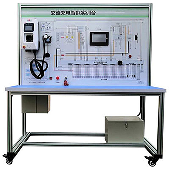
1. Install real 220V7KW national standard charging piles, lithium battery packs and charge and discharge management systems, CAN car chargers , discharge simulation load systems, ignition switches, charging pile (decomposition) components, and charging pile smart charging cards , working condition indicator light, power switch, battery and other modules and control switches, charging pile charging port, etc., a truly operable charging system.
2. The panel is made of 4mm thick aluminum-plastic plate, and the vertical installation panel is printed with a color circuit diagram and a schematic diagram of the working principle; students can visually compare the system structure schematic diagram and the actual object to understand and analyze the working principle of the system. There are detection terminals installed on the panel, which can directly detect the electrical signals of system circuit components on the panel, such as resistance, voltage, current, frequency signals, etc.
3. Charging pile indicators: Install a 220V7KW charging pile display device to display data simultaneously. The operating software displays charging voltage, charging current, charging power, charging time, etc.; it has three charging modes: charging by amount, charging by time, charging by power, etc. Safety protection function, including input side overvoltage and undervoltage protection, output side overvoltage and overcurrent protection, overtemperature, short circuit, leakage, lightning protection, and battery anti-reverse connection protection. It has three status indicators: power, charging and fault. The core control board can realize the collection and processing of card swiping information; LTE (4G), GSM multi-mode communication transmission, GPS positioning, radio frequency identification card system, current and voltage parameter collection, processing and display or alarm; power consumption collection and measurement, protection and other functions.
4. Realize the real charging process of the actual vehicle, including the detection, confirmation and wake-up process of CC signal and CP signal, temperature, current and voltage detection during the charging process, etc. 5. The charging equipment can provide real charging operation for electric vehicles or other new energy vehicle
equipment installed with national standard sockets . 6. Realize the complete and optimal charging process of charging gun handshake, charger and BMS sending and receiving messages. 7. The installation of a fault simulation system can realize fault setting and diagnosis and elimination of low-voltage circuit systems. It can set up 12 common fault settings and assess fault points. 8. The equipment frame is constructed of two integrated all-aluminum alloy profiles, 40mm×40mm and 40mm×80mm, which are oil-resistant, corrosion-resistant and easy to clean. The table is 40CM wide and paved with 32mm thick colored high-density composite boards, which is durable and rust-free. , with 4 swivel casters with self-locking devices for easy movement. 9. It is equipped with teaching materials such as practical tr*ning guides, which fully describe the working principles, practical tr*ning projects, fault settings and analysis and other key points. 10. Install a 7-inch touch color screen to display charging and discharging status information. 11. Mechanical assembly and fitter assembly virtual simulation software: This software is developed based on unity3d, with optional 6-level image quality. It is equipped with the design and virtual disassembly and assembly of reducers and shafting structures, the design and simulation of common mechanical mechanisms , and a mechanism resource library. For a typical mechanical mechanism (virtual disassembly and assembly of a gasoline engine), the software is a whole software and cannot be individual resources. A. Reducer design and virtual disassembly interface can choose worm gear bevel gear reducer, two-stage expanded cylindrical gear reducer, bevel cylindrical gear reducer, coaxial cylindrical gear reducer, bevel gear reducer, and one-stage cylindrical gear reducer. Gear reducer. Worm bevel gear reducer: After entering the software, the assembly content is automatically played. Each step in the video has a text description . Secondary expandable cylindrical gear reducer: After entering the software, the content is played in the form of a video. The video content should include: Part name ( Scan the QR code to see the names of parts), disassembly and assembly demonstration (including disassembly and assembly), virtual disassembly (including overall, low-speed shaft, medium-speed shaft, high-speed shaft, box cover, box seat) conical cylindrical gear reducer, Coaxial cylindrical gear reducer, bevel gear reducer, first-level cylindrical gear reducer: click to enter and automatically jump to the edrawings interface. The models are all three-dimensional models . By clicking on the parts, the names of the parts are displayed, and the 360° view is av*lable Rotate, enlarge, reduce, translate, and at the same time, the entire reducer can be disassembled and assembled through the moving parts function. At the same time, you can select the home button to return to the original state of the reducer. The bevel gear reducer and the first-stage cylindrical gear reducer have added the function of inserting a cross section, and the cross section can be freely dragged to observe the internal structure of the reducer. B. Shaft structure design and virtual disassembly and assembly interface optional parts recognition, disassembly and assembly demonstration, and actual operation. 1. Parts recognition: three-dimensional model and part name including helical gear, non-hole end cover, coupling, coupling key, shaft, gear key, hole end cover, shaft sleeve, deep groove ball bearing, any All parts can be rotated 360° 2. Disassembly and assembly demonstration: There are 2 built-in cases. When you move the mouse to the position of a cert*n part (except the base and bearing seat), the part will automatically enlarge and the name of the part will be displayed. It is equipped with disassembly and Assembly button, the function is to automatically complete the disassembly and assembly of the shaft system structure by the software. All three-dimensional scenes can be rotated, enlarged, reduced and translated 360° in all directions. 3. Practical operation: The three-dimensional parts are neatly placed on the table. Students manually select the corresponding parts and move them to the shaft system structure. The parts can be installed only when they are placed in the correct order and in the correct position. There is a restart button to facilitate students to restart. Conduct virtual experiments. When you move the mouse to a cert*n part position (except the base and bearing seat), the part will automatically enlarge and the part name will be displayed. C. Common mechanical mechanism design and simulation, optional hinge four-bar mechanism design and analysis, I\II type crank rocker mechanism design and analysis, offset crank slider mechanism design and analysis, crank swing guide rod mechanism design and analysis, hinge Four-bar mechanism with integrated trajectory, eccentric linear-acting roller push rod cam , and centering linear-acting flat-bottomed push rod cam . 1. Each mechanism should be able to input corresponding parameters, and the software can automatically calculate the parameters, and can perform motion simulation and automatically draw curves.
D. The mechanism resource library includes 11 types of planar link mechanisms, 5 types of cam mechanisms, 6 types of gear mechanisms, 8 types of transmission mechanisms, 11 types of tightening mechanisms, 6 types of gear tr*n mechanisms, and 8 types of other mechanisms (mechanical equipment simulation)
E , virtual disassembly and assembly of gasoline engines, optional crankcase assembly and disassembly demonstration, crankcase virtual assembly, valve tr*n assembly and disassembly demonstration, valve tr*n virtual assembly
1. Crankcase assembly and disassembly demonstration and valve tr*n assembly and disassembly demonstration both have disassembly button, assembly button, restart, and decomposition observation button. When the mouse is moved to a cert*n part position, the part will automatically enlarge and the part name will be displayed. The software automatically completes the disassembly and assembly of the shaft system structure. When using the decomposition observation button, the 3D model of the crankcase or gas distribution system automatically displays an exploded view, which can be rotated, enlarged, reduced, and translated 360°.
2. The 3D parts of the crankcase virtual assembly and the gas distribution system virtual assembly are neatly arranged When placed on the desktop, students manually select the corresponding parts and move them to the mechanism. The parts can be installed only when they are placed in the correct order and in the correct position. There is a restart button to facilitate students to re-perform the virtual experiment. When you move the mouse to cert*n part locations, the part names are automatically displayed.
3. Technical specifications
1. Power supply: AC220V ±10% 50Hz
2. Power supply current: maximum 32A
3. Working temperature: -40℃~+50℃
4. Charging pile: 220V, 7KW, 32A
5. Overall dimensions (mm) : 1500×700×1700 (length×width×height)
6. Panel dimensions (mm): 1448×940mm (length*width)
7. Mobile casters: 100*60mm
4. Practical tr*ning (experiment) items
1. Charging pile Practical tr*ning on internal and external circuit principles.
2. Practical tr*ning on the components and functions of charging piles.
3. Practical tr*ning on how to operate charging piles.
4. Practical tr*ning on operating the charging pile to charge the battery.
5. Practical tr*ning on charging system structure and principles.
6. Practical tr*ning on fault setting, troubleshooting ideas and methods.
7. Charging gun handshake, vehicle charger and BMS CAN message sending and receiving verification.
8. Practical tr*ning on BMS structure and principles of battery management system (including SOC estimation and SOH estimation information, etc.).
five. Basic configuration
detection control panel (equipped with various detection terminals, color circuit diagram and working principle diagram), charging pile components (national standard 220V 32A, 7KW), national standard AC charging socket and charging gun, smart charging card, battery management system (battery management System, with CAN bus communication/CC, CP control line, 7-inch touch color screen, charging wake-up signal control), lithium battery pack (16 strings, 3.2V20AH single battery), analog indicator light, operating switch, DC-DC conversion module (48V-12V15A), DC contactor (including charging relay, total positive relay, total negative relay, precharge relay), vehicle charger with CAN communication, emergency stop switch and m*n power switch, auxiliary battery (12V45AH), linear Adjustable discharge load, integrated all-aluminum alloy profile mobile stand (1500×700×1700mm with self-locking casters, principle panel with detection terminals, panel 1448×940mm), fault simulation and troubleshooting device, equipment operation manual.


 Wechat scan code follow us
