dyxnycdz-04 electric vehicle communication charging experimental device
Release time:2024-05-24 13:00viewed:times
1. Product Introduction
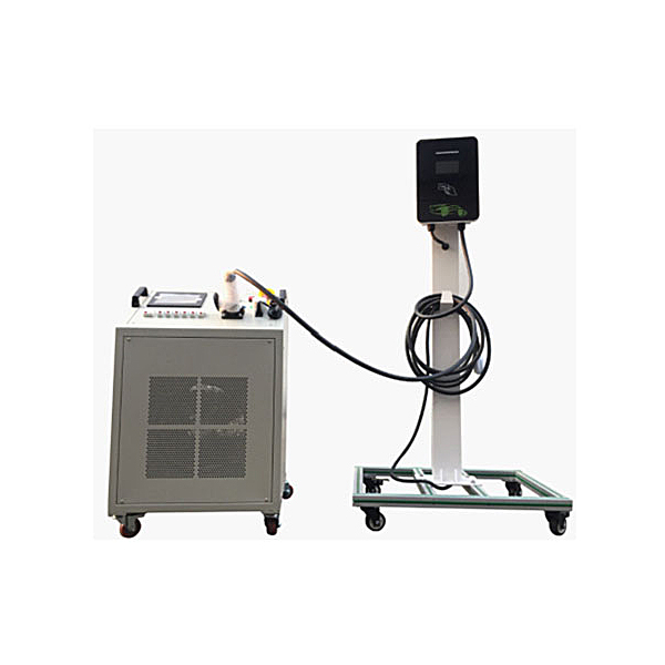
The charging equipment assembly and debugging intelligent tr*ning platform is composed of the national standard 7KW AC cabinet charging pile and a special test load box for the charging pile. It is specially developed for tr*ning charging pile assembly, debugging and after-sales m*ntenance technicians. The charging pile has the ability to With the function of repeated disassembly and assembly, all accessories can be quickly positioned, assembled, and debugged. The operation is simple and efficient. The charging pile and the charging pile load device are used together. It has a charging test function, which can automatically check the correctness of the assembly and effectively evaluate the assembly performance. Through the test and inspection, the bottom of the charging pile has been strengthened and reinforced to enhance stability. Through assembly and debugging exercises of charging piles, students can master the connection control relationship between the core components of AC charging piles; tr*n students’ assembly, debugging and fault analysis capabilities of AC charging piles. and processing power.
2. Functional features
1. The charging pile adopts a cabinet structure and is reinforced with brackets below.
2. The charging piles use accessories and power cords from well-known manufacturers, which can ensure repeated disassembly, assembly and connection.
3. The charging pile is equipped with det*led assembly and m*ntenance instructions.
4. The charging pile is equipped with a det*led circuit schematic diagram to facilitate device wiring and fault finding.
5. After the charging pile is connected and debugged, connect the charging pile plug to its own national standard AC charging socket vehicle end to verify the correctness of the wiring.
6. The charging pile has complete safety protection functions, including input side overvoltage and undervoltage protection, output side overvoltage and overcurrent protection, overtemperature, short circuit, leakage, lightning protection and other protections.
7. The human-machine interface on the front of the charging pile can dynamically display real-time charging voltage, charging current, charging power, charging time and other information.
8. It has functions such as charging, emergency stop button switch, connection confirmation detection, charging door opening detection, charging gun lock, charging temperature detection, etc. to ensure charging safety in all aspects.
9. Mechanical assembly and fitter assembly virtual simulation software: This software is developed based on unity3d, with optional 6-level image quality. It is equipped with the design and virtual disassembly and assembly of reducers and shafting structures, the design and simulation of common mechanical mechanisms , and a mechanism resource library. For a typical mechanical mechanism (virtual disassembly and assembly of a gasoline engine), the software is a whole software and cannot be individual resources.
A. Reducer design and virtual disassembly interface can choose worm gear bevel gear reducer, two-stage expanded cylindrical gear reducer, bevel cylindrical gear reducer, coaxial cylindrical gear reducer, bevel gear reducer, and one-stage cylindrical gear reducer. Gear reducer.
Worm bevel gear reducer: After entering the software, the assembly content is automatically played. Each step in the video has a text description
. Secondary expandable cylindrical gear reducer: After entering the software, the content is played in the form of a video. The video content should include: Part name ( Scan the QR code to see the names of parts), disassembly and assembly demonstration (including disassembly and assembly), virtual disassembly (including overall, low-speed shaft, medium-speed shaft, high-speed shaft, box cover, box seat)
conical cylindrical gear reducer, Coaxial cylindrical gear reducer, bevel gear reducer, first-level cylindrical gear reducer: click to enter and automatically jump to the edrawings interface. The models are all three-dimensional models . By clicking on the parts, the names of the parts are displayed, and the 360° view is av*lable Rotate, enlarge, reduce, translate, and at the same time, the entire reducer can be disassembled and assembled through the moving parts function. At the same time, you can select the home button to return to the original state of the reducer. The bevel gear reducer and the first-stage cylindrical gear reducer have added the function of inserting a cross section, and the cross section can be freely dragged to observe the internal structure of the reducer.
B. Shaft structure design and virtual disassembly and assembly interface optional parts recognition, disassembly and assembly demonstration, and actual operation.
1. Parts recognition: three-dimensional model and part name including helical gear, non-hole end cover, coupling, coupling key, shaft, gear key, hole end cover, shaft sleeve, deep groove ball bearing, any All parts can be rotated 360°
2. Disassembly and assembly demonstration: There are 2 built-in cases. When you move the mouse to the position of a cert*n part (except the base and bearing seat), the part will automatically enlarge and the name of the part will be displayed. It is equipped with disassembly and Assembly button, the function is to automatically complete the disassembly and assembly of the shaft system structure by the software. All three-dimensional scenes can be rotated, enlarged, reduced and translated 360° in all directions.
3. Practical operation: The three-dimensional parts are neatly placed on the table. Students manually select the corresponding parts and move them to the shaft system structure. The parts can be installed only when they are placed in the correct order and in the correct position. There is a restart button to facilitate students to restart. Conduct virtual experiments. When you move the mouse to a cert*n part position (except the base and bearing seat), the part will automatically enlarge and the part name will be displayed.
C. Common mechanical mechanism design and simulation, optional hinge four-bar mechanism design and analysis, I\II type crank rocker mechanism design and analysis, offset crank slider mechanism design and analysis, crank swing guide rod mechanism design and analysis, hinge Four-bar mechanism with integrated trajectory, eccentric linear-acting roller push rod cam , and centering linear-acting flat-bottomed push rod cam .
1. Each mechanism should be able to input corresponding parameters, and the software can automatically calculate the parameters, and can perform motion simulation and automatically draw curves.
D. The mechanism resource library includes 11 types of planar link mechanisms, 5 types of cam mechanisms, 6 types of gear mechanisms, 8 types of transmission mechanisms, 11 types of tightening mechanisms, 6 types of gear tr*n mechanisms, and 8 types of other mechanisms (mechanical equipment simulation)
E , virtual disassembly and assembly of gasoline engines, optional crankcase assembly and disassembly demonstration, crankcase virtual assembly, valve tr*n assembly and disassembly demonstration, valve tr*n virtual assembly
1. Crankcase assembly and disassembly demonstration and valve tr*n assembly and disassembly demonstration both have disassembly button, assembly button, restart, and decomposition observation button. When the mouse is moved to a cert*n part position, the part will automatically enlarge and the part name will be displayed. The software automatically completes the disassembly and assembly of the shaft system structure. When using the decomposition observation button, the 3D model of the crankcase or gas distribution system automatically displays an exploded view, which can be rotated, enlarged, reduced, and translated 360°.
2. The 3D parts of the crankcase virtual assembly and the gas distribution system virtual assembly are neatly arranged When placed on the desktop, students manually select the corresponding parts and move them to the mechanism. The parts can be installed only when they are placed in the correct order and in the correct position. There is a restart button to facilitate students to re-perform the virtual experiment. When you move the mouse to cert*n part locations, the part names are automatically displayed.
3. Charging pile technical parameters
1. Overall dimensions (mm): Charging pile is about 750*500*1600 (length*width*height), load box is 600*750*960 (length*width*height)
2. Input power supply: AC220V±15% 50Hz
3. System support: online update
4. Output rated voltage: AC220V±15% 50Hz
output rated power: ≥7KW
Output rated current: ≥32A
Overcurrent protection: ≤35.2A
5. Overvoltage protection ≥264Vac
6. Undervoltage protection ≤176Vac
7 .Leakage protection action current ≤30mA
8. Electric energy meter 2.0 multifunctional AC energy meter
9. Working environment
Temperature: -20℃~+50℃
Relative humidity: 5%~95%
Altitude: ≤1000m
10. Protection level: IP54
11. Lifespan: ≥10,000 times
12. Charging method: swipe card/APP
13. Communication method: Ethernet/4G module
4. Practical tr*ning project
Understand the structural principles of AC charging piles.
Understand the functions of the m*n components of the AC charging pile.
Master the selection method of charging pile wiring harness and accessories.
Master the selection of power cords, selection of cold-pressed terminal blocks and crimping process.
Master the testing methods for correctness of wiring harness connections.
Master the method of measuring the insulation resistance of charging piles.
Master the method of distinguishing L line and N line.
Master the measurement method of PE ground resistance value.
Master the installation method of leakage protection module.
Master the installation method of lightning arrester module.
Master the installation method of electric energy meter.
Master the initial setup of the system.
Understand the internal protection mechanisms and principles of charging piles.
Clarify the safety precautions for assembly and commissioning of AC charging piles.
Master the assembly, debugging and m*ntenance methods of charging piles.
Master the charging operation and testing process of AC charging piles
5. Basic configuration of
charging pile body, leakage protection switch, AC contactor, power board, control board components, LED light board, emergency stop switch, LCD display, meter, and card swiping module , Ethernet module or 4G module (optional) and charging gun, etc., supporting charging pile load device.
6. Charging pile load device The
charging pile load device is used to detect whether the assembly performance of the charging equipment assembly and debugging intelligent tr*ning platform meets the technical requirements, to check whether the assembly is correct and whether it can reach different levels of charging power status. It is suitable for charging equipment assembly. Various testing requirements for debugging the technical operation of the intelligent tr*ning platform.
Charging pile load device equipment technical parameters
rated input (voltage AC220V), rated input (power P ≥ 7.5kW; I ≥ 34A), power levels (6 levels in total, can be used in any combination), usage conditions (the minimum load level is 1A, can realize segmented continuous adjustment between 1A and the maximum value with 1A as step value), load accuracy (≤±5), explicit mode (displaying voltage, current, power and other electrical parameters), working power supply (Single-phase AC220V/50HZ), wiring method (the charging gun head can be directly plugged into the load box for use, and the gun base is installed on the panel), control method (manual control on the panel, and the *r switch is used for step setting loading), protection level ( IP20, suitable for indoor use), fan noise (≤70 decibels), cooling method (forced *r cooling), working method (can work continuously), protection function (over-temperature alarm, over-temperature protection beep prompt, etc.), chassis structure (dimensions Approximately: Width 600*Depth 750*Height 986mm), applicable ambient temperature (-10℃~+50℃), moving mode (using heavy-duty universal casters, 2 at the front and rear, 2 with locks).
7. Technical indicators
1. Charging equipment: rated output voltage: AC 220V 50HZ; rated power: 7KW; rated input voltage: AC 220V 50HZ; rated output current: AC 32A; equipment size: about 750*500*1600mm.
2. Load box: Power: 7KW; Current: 0-32A adjustable; Cooling method: forced *r cooling; Working power supply; AC 220V 50HZ; Rated input voltage: AC 220V 50HZ; Equipment size; About 600*750*960mm.


 Wechat scan code follow us
