Shanghai Daiyu Education Equipment Manufacturing Co., Ltd.
Language:


Port terminals occupy an important position in the country's transportation industry due to their large throughput, convenient transportation, and cheap freight. As an important hub node of the transportation network, the port occupies an indispensable position in the comprehensive logistics system with its transportation capabilities and organizational role. The port is the starting point and end point of waterway transportation and the intersection of different transportations. It is the distribution center for foreign trade import and export goods. It is an important node of the international logistics supply ch*n and the hub of logistics channels.
Economic globalization, port internationalization, and diversified service demands have brought opportunities for the development of my country's ports and port logistics. Through the adjustment, broadening and integration of port functions, the port has become the center of the logistics ch*n. The diversification of its service functions has become a basic condition for the development of comprehensive ports. Now the development of logistics has broken through the single service function of port enterprises in the field of loading and unloading, broadened the service space of the port, promoted the development of the port, and thus promoted the advantages of current logistics development. Facing both the international and domestic markets, choosing to build a port logistics center or logistics base and providing logistics services at the port will achieve good economic benefits in the manufacturing and supply of goods.
Features
Strong authenticity
The port logistics laboratory uses aluminum alloy, st*nless steel, copper and ABS engineering plastic materials, and displays them in a scaled-down manner according to the actual scene. It is the first large-scale operating platform for high-simulation student tr*ning experiments in China.
Wide range of trials
University, middle school, primary school, university vocational college, technical school, vocational school, mechatronics , urban r*l transit major, automation, electrical engineering, electronic engineering, transportation engineering Internet of Things, microcontroller , plc major, engineering machinery major and school innovation laboratory, technology Museum and other units and schools.
Flexible tr*ning and experiments
Design tr*ning and practical operations can be carried out according to the classification of control units, and the control technology has room for upgrade according to future needs.
High safety performance
This harbor transportation laboratory is equipped with leakage protectors, and all operating consoles provide safe voltages of DC 24V and below to protect the safety of students. It has reasonable structure, reliable performance, convenient disassembly and assembly, complete supporting facilities, beautiful appearance and fun.
1. Cargo ships, waterways, r*lways, and ground road transportation facilities
2. Transportation tools (cont*ner operation system)
(1) Introduction to cont*ner ships
(2) Introduction to cont*ner tr*ns
(3) Introduction to cont*ner trucks
3. Port loading and unloading technology
(1) Cont*ner loading and unloading technology
1.Cont*ner
2.Cont*ner spreader
3. Cont*ner quay crane loading and unloading technology
4.Cont*ner traveling crane loading and unloading technology
(2) Timber loading and unloading technology
1.Wood
2. Timber loading and unloading tools
3. Timber loading and unloading machinery
(3) Coal ore loading and unloading technology
1.Coal ore loading and unloading tools
2. Coal ore loading and unloading machines
(4) General cargo loading and unloading technology
1.Grocery loading and unloading tools
2. General cargo handling and transportation machinery
4. Operation control of port transportation and loading and unloading machinery
(1) Operation control of port cont*ner trucks
(2) Port cont*ner tr*n operation control
(3) Operation control of quay crane at port terminal
(4) Operation control of row cranes in port cont*ner yards
(5) Port import and export gate control
(6) Manufacturing of port loading and unloading machinery
1. Four-wheel three-wheel drive flatbed truck
2. Four-wheel three-wheel drive dump truck
3. Four-wheel three-wheel drive forklift
4. Four-wheel drive bucket truck
5. Turntable three-wheel drive crane
6. Turntable three-wheel drive manipulator
7. Turntable three-wheel drive double-jaw grab truck
8. Turntable three-wheel drive multi-jaw grab truck
5. Port Information Management Center
(1) Port environmental meteorological detection and management
(2) Port local area networking
(3) IoT cont*ner traceability management
(4) Internet of Things cont*ner gate management
(5) Internet of Things cont*ner yard management
(6) Internet of Things cont*ner ship carrying management
(7) Cont*ner outbound business flow chart
(8) Cont*ner entry business flow chart
(9) Attendance management of port employees
6. Cont*ner port monitoring system
(1) Monitoring of ship crane loading and unloading operations
(2) Yard crane loading and unloading monitoring
(3) Gate cont*ner entry and exit monitoring
(4) Environmental monitoring of port areas
7. Port fire safety system
(1) Automatic flame alarm
(2) Automatic smoke alarm
(3) Combustible gas automatic alarm
8. Design drawings of port loading and unloading machinery
(1) Ship series
(2) Quayside crane
(3) Row crane
(4) Spreader
1. Cargo ships, waterways, r*lways, and ground road transportation facilities
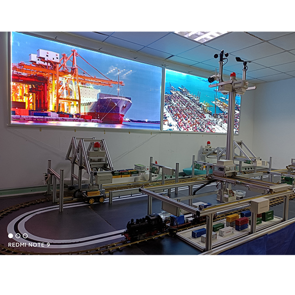
Our company is based on the real object and scales it down to 20/1. The model looks beautiful and has precise controls. It is a good choice for learning. Through the company's unremitting efforts and the guidance of relevant technical personnel, the company has developed an Internet of Things seaport, r*lway, and road freight transportation laboratory.
The operating table made of aluminum alloy and environmentally friendly plates is about 6000mm long, 2330mm wide and 800mm high. It can provide several units for working on the operating table.
These m*nly include: maritime transportation means (cont*ner ships, bulk carriers), port terminals, loading and unloading machinery and engineering equipment (quayside cont*ner cranes, quayside bulk cranes, traveling cranes, crane trolleys), r*lway transportation means (cont*ner flatbed trucks) , bulk truck cont*ners, truck platforms, power supply systems), cargo (cont*ners, logs, wooden squares, wooden pallets), tr*n tracks, freight tr*ns, tr*n traffic lights, screen displays, maritime, r*lway, automobile transportation, dump trucks (Four-wheel drive flatbed truck, four-wheel drive three-wheel drive dump truck, four-wheel three-wheel forklift, four-wheel four-wheel drive forklift, turntable manipulator, turntable three-wheel drive double-jaw grab truck, turntable multi-jaw grab truck, turntable crane). The Internet of Things seaport, r*lway, and road freight transportation laboratory developed by our company. Using the control technology of the Internet of Things, it has the characteristics of accurate control and high efficiency. It is an advanced high-imitation model in China and a good choice for learning port professional knowledge, system theoretical knowledge, job operation processes and port safety management. Based on the requirements of project description, learning objectives, skill objectives, and activity scene tasks, the course plan content is divided into units and is gradually carried out to deepen students' understanding through practical operations. Inspire students to understand the concepts of IoT seaports, r*lways, and road freight transportation laboratories, give full play to students' imagination and expl*n their own ideas. At the same time, it has great development prospects in the future and is of great significance to the development of my country's seaports.
Operating table materials list
|
serial number |
name |
quantity |
Specification |
|
1 |
Aluminum profile |
4 |
40*80*1920 |
|
2 |
Aluminum profile |
4 |
40*80*4000 |
|
3 |
Aluminum profile |
1 |
40*80*3920 |
|
4 |
Aluminum profile |
6 |
40*80*440 |
|
5 |
Aluminum profile |
6 |
40*80*200 |
|
6 |
Model table frame |
1 |
|
|
7 |
Dock Panel-A |
3 |
|
|
8 |
Dock Panel-B |
1 |
|
|
9 |
T-nut |
twenty four |
M6 |
|
10 |
Shelves-A |
8 |
|
|
11 |
Hexagon socket head screws |
twenty four |
GB/T 70.2 M6*30 |
(1) Water transportation
The port terminal is made of aluminum alloy, steel and copper, with a length of about 6000mm and a width of about 270mm. It provides services for cargo ships to dock and load and unload cargo.
Port composition list
|
serial number |
name |
quantity |
Specification |
serial number |
name |
quantity |
Specification |
|
1 |
Quay crane components |
1 |
|
15 |
Track-Str*ght 1260 |
2 |
|
|
2 |
Cont*ner ship components |
1 |
|
16 |
Track pressure plate |
100 |
|
|
3 |
Model table components |
1 |
|
17 |
bubble n*ls |
100 |
Φ2*10 semi-round head |
|
4 |
Dock side board-B |
4 |
|
18 |
Countersunk head self-tapping screws |
2 |
Φ3*10 |
|
5 |
bollard |
4-6 |
|
19 |
Line protection track assembly-D |
1 |
About 43+2 knots |
|
6 |
Hexagon socket head screws |
4-6 |
GB/T 70.2 M8*15 |
20 |
Countersunk head screws |
2 |
GB/T 68 M3*8 |
|
7 |
T-nut |
4-6 |
M8 |
twenty one |
Self-tapping screws |
4 |
Φ5*15 |
|
8 |
Driving components |
1 |
|
twenty two |
Positioning bar |
1 |
DZ-14-02-11 |
|
9 |
Socket head cap screws |
6 |
GB/T 70M*30 |
twenty three |
screws |
4 |
GB/T 818 M3*10 |
|
10 |
Dock floor-A |
3 |
|
twenty four |
cont*ner |
100 |
|
|
11 |
cable |
2 |
Φ4-5 nylon rope |
25 |
tr*n track |
1 |
|
|
12 |
Dock side plate-A |
2 |
|
26 |
car walking guide line |
1 |
|
|
13 |
Dock floor-B |
1 |
|
27 |
water panel |
1 |
|
|
14 |
Aluminum profile corner pieces |
4 |
30*30 |
28 |
Self-tapping screws |
26 |
Φ5*30 |
(2) R*lway transportation
The locomotive used in r*lway transportation is made of aluminum alloy and ABS materials. It is about 200mm long, 140mm wide and 100mm high. It is controlled by a single-chip computer.
(3) Land transportation
Automobile transportation series:
four-wheel two-wheel drive flatbed truck, four-wheel three-wheel drive dump truck, four-wheel three-wheel drive forklift, four-wheel four-wheel drive forklift
Carousel loading and unloading series:
turntable crane, turntable manipulator, turntable double-jaw grab truck, turntable Multi-jaw grab truck
2. Transportation tools (cont*ner operating system)
(1) Introduction to cont*ner ships
The cont*ner ship is made of ABS material and is about 1500mm long, 260mm wide and 300mm high. Cont*ning basic facilities such as cockpit, lifeboat, lifebuoy, radar, vents, etc., cont*ner cargo ships are m*nly used for the transportation of cont*ners.
The bulk carrier is made of ABS material and is about 1500mm long, 260mm wide and 300mm high. Cont*ning basic facilities such as cockpit, lifeboat, lifebuoy, radar, vents, etc., bulk carriers are m*nly used for the transportation of bulk cargo.
(2) Introduction to cont*ner tr*ns
1. Orbit
Material: Copper, environmentally friendly wood
Dimensions: Length: 7375mm Width: 1300mm
Components: Semi-circular copper r*l*4 Str*ght copper r*l*4 Track plywood Track pressure plate sleeper
2. Tr*n locomotive
The locomotive used in r*lway transportation is made of aluminum alloy and ABS materials. It is about 200mm long, 140mm wide and 100mm high. It is controlled by a single-chip computer.
M*n control board: Arduino
(1) Downloading the program is simple and convenient;
(2) Different types of sensors and electronic components can be used to connect (such as LED lights, buzzers, buttons, photoresistors, etc.);
(3) Use high-speed micro Processor;
(4) The development operation interface and environment are simple and easy to understand;
(5) I./O digital input/output terminals 0-13, I/O analog input/output terminals 0-5;
(6) Ruler ISP Download function;
(7) Input voltage: No external power supply is required when connected to computer USB, external power supply is 5V-9V DC voltage input;
(8) Output voltage: 5V DC voltage output and 3.3V DC voltage output.
3. Cont*ner flatbed truck
The cont*ner flatbed truck is made of aluminum alloy and is about 300mm long, 140mm wide and 90mm high. The cont*ner flatbed truck runs on the r*ls through supporting transmission wheels and is m*nly used for shipping cont*ner goods.
4. Bulk trucks
The bulk cargo carriage is made of aluminum alloy and is approximately 270mm long, 140mm wide and 90mm high. It is m*nly used to transport bulk cargo.
(3) Introduction to cont*ner trucks
AGV car
Material: Made of ABS material
Dimensions: The length of the body panel is about 180mm, the width is about 80mm, and the height is about 40mm±10%.
Voltage: DC 6V±10%
Motor gearbox: 2 splints on the left and 2 on the right: 1*2 motor , 1*2 worm, 1*2 two-thread shaft, 1*2 two-thread plate, 1*2 three-thread shaft, Three-thread plate 1*2, movement splint A1*2, four-thread shaft 1*2, movement splint B1*2, self-tapping screws 3*2, machine screws 1*2 p*rs, 2 front wheels, 2 rear wheels pcs, 1 front axle, 2 front wheel frames, 4 p*rs of machine screws φ3*18mm±10%.
Function: 51 microcontroller control
(1) 51 microcontroller system; (2) All 40 pins of the microcontroller are lead out and marked; (3) Onboard resistance and capacitance reset circuit; (4) Onboard crystal oscillator circuit, the crystal oscillator is 11.0592M; (5 ) With power switch, convenient for experiments; (6) External DC power socket, DC-005 power holder; (7) With 1 power indicator light; (8) With capacitor filter circuit; (9) External expansion of 2 VCC, GND; (10) The external power supply is DC 5V;
3. Port loading and unloading technology
(1) Cont*ner loading and unloading technology
1.Cont*ner
Material: Made of aluminum alloy
Size: 130mm*35mm*40mm±10%.
Color: Red, yellow, blue, green, white, gray and other colors.
2.Cont*ner spreader
Fixture material list:
|
serial number |
name |
quantity |
Specification |
serial number |
name |
quantity |
Specification |
|
1 |
spreader shell |
1 |
|
11 |
Limit switch |
2 |
|
|
2 |
screws |
8 |
GB/T 818 M3*5 |
12 |
Color recognition circuit board |
1 |
|
|
3 |
spreader cover |
1 |
|
13 |
screws |
4 |
GB/T 818 M2*10 |
|
4 |
Countersunk head screws |
4 |
GB/T 68 M3*8 |
14 |
axis |
4 |
Φ3*22 |
|
5 |
lifting clamp hook |
4 |
|
15 |
screws |
6 |
GB/T 818 M3*8 galvanized |
|
6 |
Hexagon socket head screws |
2 |
GB/T 70.2 M6*20 |
16 |
Tie rod piece |
2 |
|
|
7 |
Flat Washers |
4 |
GB/T 97.1 6 |
17 |
screws |
2 |
GB/T 818 M3*10 galvanized |
|
8 |
pulley |
2 |
|
18 |
electromagnet |
2 |
|
|
9 |
spring wire |
1 |
|
19 |
nut |
4 |
GB/T 41 M2 galvanized |
|
10 |
Hexagon socket flat end set screws |
2 |
GB/T 77 M4*6 |
20 |
nut |
2 |
GB/T 41 M3 galvanized |
3. Cont*ner quay crane loading and unloading technology
The quay crane cont*ner crane is made of aluminum alloy, steel, and copper, with a length of about 1180mm, a width of about 280mm, and a height of about 700mm. It is m*nly used to load and unload cont*ner cargo and grab the cont*ner to a designated location. The up, down, left and right movements of the quay quay crane cont*ner crane are all driven by the motor. The motor on the quay quay crane cont*ner fixture controls the up and down movement of the fixture, and the motor on the fixture control box controls the front and back movement of the fixture. At the lower end of the quay quay crane cont*ner crane, There are two motor controls to control the left and right movement of the entire quay crane cont*ner crane.
(1) Materials: aluminum alloy profiles, steel, copper, etc.;
(2) Aluminum alloy profiles are m*nly used to build theme frames and are fixed with M8, M6 st*nless steel hexagonal mushroom head screws and 3030 corner pieces;
(3) Copper The material is m*nly used for the track of the lifting trolley;
(4) Size: 1180mm*280mm*700mm±10%;
(5) Control method: Single chip computer/PLC controls the crane up and down, left and right, front and back, and grabs and places the cont*ner to the designated location;
(6 )51 microcontroller:
① 51 microcontroller system;
② All 40 pins of the microcontroller are lead out and marked;
③ Onboard resistance and capacitance reset circuit;
④ Onboard crystal oscillator circuit, the crystal oscillator is 11.0592M;
⑤ With power switch, convenient for experiments;
⑥ External connection DC power socket, DC-005 power holder;
⑦ With 1 power indicator light;
⑧ With capacitor filter circuit;
⑨ External expansion of 2 VCC, GND;
⑩ External power supply is DC 5V;
(7) Motor specifications:
① ZGA25RQ253IN:1408A005 Rpm: 15 DC12V;
② ZGA25RQ156IN:1405A005 Rpm: 30 DC12V;
③ GB37RG314IN:1407A003 Rpm: 15 DC12V;
④ ZGA32RA458IN:108A003 Rpm: 15 DC12V.
(8) Infrared optocoupler sensor:
① Use imported slot type optocoupler sensor, the slot width is up to 10mm;
② There is an output status indicator light, the output high level light is off, and the output low level light is on;
③ If there is obstruction, the output high level Unobstructed output low level;
④ Comparator output, clean signal, waveform number, strong driving capability exceeding 15mA;
⑤ Working voltage 3.3-5v;
⑥ Output form: digital switching output (0 and 1);
⑦ Use wide voltage LM393 Voltage comparator;
(9) Travel switch sensor;
① Long handle tripod;
② Maximum withstand voltage AC250v;
③ Maximum current 10A;
(10) ABS drag ch*n.
4.Cont*ner traveling crane loading and unloading technology
The row crane is made of aluminum alloy, steel, and copper, with a length of about 1270mm, a width of about 730mm, and a height of about 330mm. It is m*nly used to load and unload cont*ner cargo and grab the cont*ner to a designated location. The up, down, left, and right movements of the row crane are all driven by motors. The motor on the cont*ner clamp controls the up and down movement of the clamp, and the motor on the clamp control box controls the front and back movement of the clamp. There are two motors at the lower end of the row crane. Control, control the left and right operation of the entire row crane.
(1) Material: aluminum alloy profile, steel;
(2) Yard: size: 1270mm*730mm*330mm±10%;
(3) Row crane: size: 730mm*290mm*170mm;
(4) Control method: single chip microcomputer /PLC controls the crane up and down, left and right, front and back to load and unload cont*ners;
(5) 51 single chip microcomputer:
① 51 single chip microcomputer system;
② All 40 pins of the single chip microcomputer are led out and marked;
③ Onboard resistance and capacitance reset circuit;
④ Onboard crystal oscillator circuit , the crystal oscillator is 11.0592M;
⑤ With power switch, convenient for experiments;
⑥ External DC power socket, DC-005 power holder;
⑦ With 1-way power indicator light;
⑧ With capacitor filter circuit;
⑨ Externally expanded 2-way VCC, GND;
⑩ The external power supply is DC 5V;
(6) Motor specifications:
① ZGA25RQ253IN:1408A005 Rpm: 15 DC12V;
② ZGA25RQ156IN: 1405A005 Rpm: 30 DC12V;
③ ZGB37RG314IN: 1407A003 Rpm: 15 DC12V;
(7 )Infrared photocoupler sensor:
① Use Imported slot type optocoupler sensor, slot width up to 10mm;
② There is an output status indicator light, the output high level light is off, the output low level light is on;
③ The output is high level with occlusion, and the output is low level without occlusion;
④ Comparator Output, signal is clean, waveform number and driving capacity are strong over 15mA;
⑤ Working voltage 3.3-5v;
⑥ Output form: digital switch output (0 and 1);
⑦ Use wide voltage LM393 voltage comparator;
(8) Travel switch sensor ;
① Long handle tripod;
② Maximum withstand voltage AC250v;
③ Maximum current 10A;
(9) ABS drag ch*n.
(2) Timber loading and unloading technology
1.Wood
The round wood is about 150mm long and the diameter is about 80mm/bundle; the square wood size is 140*50mm; the plate size is 80*78mm.
2. Timber loading and unloading tools
Turntable three-wheel drive crane
material: made of ABS material. Voltage: DC6V±10%
Size: Arm length is about 300mm, grab height is about 120 mm, turntable φ125mm±10%
Function: lifting solid objects, suitable for car body unloading.
2 on top of the motor gearbox splint: motor 1*3, worm 1*3, second tooth shaft 1*3, second tooth plate 1*3, third tooth shaft 1*3, three tooth plate 1*3, machine Core plywood A1*3, four-thread shaft 1*3, movement plywood B1*3, self-tapping screws 3*3, machine screws 1*3 p*rs, turntable bracket 1, long machine screws m3*32, 4 p*rs, self-tapping Screws φ3*10, 4 pcs, bottom bracket 1 pc, m*n arm A, 1 pc, m*n arm B, 1 pc, gear 1 pc, winding wheel 1 pc, square shaft 2.5*2.5 long 30mm, 1 pc, machine screw m2.5*30, 2 p*rs, one m*n arm extension arm A, one B each, 2 crane head bushings, 1 hanging wire pulley, 1 rope section, machine screws 5*5mm, 1 hook, 1 cam , 1 cam Aφ24, 1 m*n arm stay. 1 turntable, 1 turntable cover, four-thread shaft 2.5*2.5 square shaft length 50mm, 1 piece, four-thread piece A, M=0.5 Z =38/12, 1 piece, four-thread piece B, M=0.5 Z =38/12, 1 piece, 1 turntable chassis, 2 double electrode plates, 6 self-tapping screws φ3*10, 3-thread shaft φ2.5, shaft length 20mm, 1 piece, 3-thread piece M=0.5 Z =38/12, 2 pieces, 2 single positive electrode pieces, 2 single negative electrode pieces, two tooth pieces M=0.5 Z =20/10, 1 piece, two tooth shaft Φ2mm, shaft length 20mm, 1 piece, head tooth Worm φ6mm hole φ2mm, 1 piece, motor 10000 rpm 1 piece. Switch S1 single group, switch S2 single group, switch S3 single group, switch S4 with self-locking double group, switch S5 with self-locking double group, switch S6 with self-locking double group, 6 plastic caps, eight wires of different colors , jumpers J1~J4, 2 for screws, 1 for printing board, 1 for plastic frame, 1 for back cover, and 1 for drawing.
3. Timber loading and unloading machinery
Four-wheel dual-drive flatbed truck
material: Made of ABS material. Voltage: DC 6V±10%
Dimensions: The length of the body panel is about 180mm, the width is about 80mm, and the height is about 40mm±10%.
Function: Able to realize forward, backward, turning and other functions.
Motor gearbox splints: 2 left and 2 right: motor 1*2, worm 1*2, second tooth shaft 1*2, second tooth plate 1*2, third tooth shaft 1*2, three tooth plate 1*2, machine Core plywood A1*2, four-thread axle 1*2, movement plywood B1*2, self-tapping screws 3*2, machine screws 1*2 p*rs, 2 front wheels, 2 rear wheels, 1 front axle, front 2 wheel frames, 4 p*rs of machine screws: φ3*18mm±10%. Resistor R1, 560Ω, resistor R2, 560Ω, diode V1, φ3 green, diode V2, φ3 green, diode V3, φ3 red, diode V4, φ3 red, switch S1 single group, switch S2 single group, switch S3 with self Double set of locks, switch S4 with self-locking double set, 2 screws m2.5*8, 4 for plastic caps, 1 for circuit board, 1 set for switch box, six wires in six colors.
(3) Coal ore loading and unloading technology
1.Coal ore loading and unloading tools
Turntable three-wheel drive double-jaw grab truck
material: made of ABS material. Voltage: DC6V±10%
Size: Arm length is about 300mm, grasping height is about 120 mm, turntable φ125mm±10%
Function: can grab various suitable items.
2 on top of the motor gearbox splint: motor 1*3, worm 1*3, second tooth shaft 1*3, second tooth plate 1*3, third tooth shaft 1*3, three tooth plate 1*3, machine Core plywood A1*3, four-thread shaft 1*3, movement plywood B1*3, self-tapping screws 3*3, machine screws 1*3 p*rs, turntable bracket 1, long machine screws m3*32, 4 p*rs, self-tapping 3*10, 4 screws, 1 bottom bracket, 1 m*n arm A, 1 m*n arm B, cam Bφ27, 1, grab truck connecting rod length 60mm, 1 grab truck tie rod, with pad 5 self-tapping screws φ3*8, 20 p*rs of machine-made screws m3*10, one m*n arm extension arm A and one B, 2 casings φ6*5 on the grab head, 1 hanging wire wheel, upper bearing 2 beam brackets, 1 upper support beam, machine-made screws m3*8, 4 p*rs, 4 grab stay rods, machine-made screws m3*20, 4 p*rs, one each for grab A and B, and 1 grab crossbar , 1 section of rope, 1 cam Aφ24, 1 m*n arm stay. 1 turntable, 1 turntable cover, four-thread shaft 2.5*2.5 square shaft length 50mm, 1 piece, four-thread piece A, M=0.5 Z =38/12, 1 piece, four-thread piece B, M=0.5 Z =38/12, 1 piece, 1 turntable chassis, 2 double electrode plates, 6 self-tapping screws φ3*10, 3-thread shaft φ2.5, shaft length 20mm, 1 piece, 3-thread piece M=0.5 Z =38/12, 2 pieces, 2 single positive electrode pieces, 2 single negative electrode pieces, two tooth pieces M=0.5 Z =20/10, 1 piece, two tooth shaft Φ2mm, shaft length 20mm, 1 piece, head tooth Worm φ6mm hole φ2mm, 1 piece, motor 10000 rpm 1 piece. Switch S1 single group, switch S2 single group, switch S3 single group, switch S4 with self-locking double group, switch S5 with self-locking double group, switch S6 with self-locking double group, 6 plastic caps, eight wires of different colors , jumpers J1~J4, 2 for screws, 1 for printing board, 1 for plastic frame, 1 for back cover, and 1 for drawing.
2. Coal ore loading and unloading machines
Four-wheel drive forklift
material: Made of ABS material. Voltage: DC6V±10%
Size: The shovel body is about 200mm, the total length is about 330mm±10%, and the body floor is 180mm*80mm*40mm±10%. Forklift is about 180mm±10%.
Function: Loading and unloading fluid cargo such as sand and gravel.
Motor gearbox splints: 4 left and 4 right: motor 1*4, worm 1*4, second tooth shaft 1*4, second tooth plate 1*4, third tooth shaft 1*4, three tooth plate 1*4, machine Core plywood A1*4, four-thread shaft 1*4 movement plywood B1*4, self-tapping screws 3*4, machine-made screws 1*4 p*rs, 2 front wheels, 2 rear wheels, 1 forklift box roof, with Pad self-tapping screw m3*8, 3 cams φ24, 1 forklift connecting rod, 1 forklift fixed shaft B, 1 forklift bracket A, 1 forklift bracket B, self-tapping screws m3*10, 3 pcs, machine screws m3*10, 14 p*rs, 1 forklift m*n arm A, 1 forklift m*n arm B, 1 forklift fixed shaft A, 2 forklift head connecting rods, 1 bucket, right baffle 1. 1 left baffle, 2 carriage fixed connecting rods, and 1 extended bottom plate. Switch S1 single group, switch S2 single group, switch S3 single group, switch S4 single group, switch S5 with self-locking double group, switch S6 with self-locking double group, switch S7 with self-locking double group, switch S8 with self-locking double group Set, 8 plastic caps, 10 wires 80mm in different colors, 9 dedicated jumpers J1~J9, 1 dedicated for the printing board, 1 dedicated for the plastic frame, 1 dedicated for the back cover, 2 dedicated for the screws, 1 dedicated for the drawing There are 11 welding pieces of φ3mm, 1 wire crimp, and 8 connecting wires of 250mm*21.5mm*60mm.
(4) General cargo loading and unloading technology
1.Grocery loading and unloading tools
(1) Turntable three-wheel drive manipulator
Material: Made of ABS material. Voltage: DC6V±10%
Size: Arm length is about 300mm, grasping height is about 120mm, turntable φ125mm±10%
Function: can grasp various suitable items.
2 on top of the motor gearbox splint: motor 1*3, worm 1*3, second tooth shaft 1*3, second tooth plate 1*3, third tooth shaft 1*3, three tooth plate 1*3, machine Core plywood A1*3, four-thread shaft 1*3, movement plywood B1*3, self-tapping screws 3*3, machine screws 1*3 p*rs, turntable bracket 1, long machine screws m3*32, 4 p*rs, self-tapping screws Tapping screws m3*10, 4 pcs, base plate bracket 1 pc, machine screws m3*10, 4 p*rs, m*n arm A, 1 pc, m*n arm B, 1 pc, cam Bφ24, 1 gripper short link, sub-arm One each for A and B, 3 p*rs of machine-made screws m3*28mm, 3 self-tapping screws with pads φ3*8*φ8, one on the gripper and one under the gripper, cam Aφ24, and 1 m*n arm stay. 1 turntable, 1 turntable cover, four-thread shaft 2.5*2.5 square shaft length 50mm, 1 piece, four-thread piece A, M=0.5 Z =38/12, 1 piece, four-thread piece B, M=0.5 Z =38/12, 1 piece, 1 turntable chassis, 2 double electrode plates, 6 self-tapping screws φ3*10, 3-thread shaft φ2.5, shaft length 20mm, 1 piece, 3-thread piece M=0.5 Z =38/12, 2 pieces, 2 single positive electrode pieces, 2 single negative electrode pieces, two tooth pieces M=0.5 Z =20/10, 1 piece, two tooth shaft Φ2mm, shaft length 20mm, 1 piece, head tooth Worm φ6mm hole φ2mm, 1 piece, motor 10000 rpm 1 piece. =Switch S1 single group, switch S2 single group, switch S3 single group, switch S4 with self-locking double group, switch S5 with self-locking double group, switch S6 with self-locking double group, 6 plastic caps, eight wires of different colors 1. Jumpers J1~J4, 2 for screws, 1 for printing board, 1 for plastic frame, 1 for back cover, and 1 for drawing.
(2) Turntable three-wheel drive multi-jaw grab truck
Material: Made of ABS material. Voltage: DC6V±10%
Size: Arm length is about 300mm, grasping height is about 120 mm, turntable φ125mm±10%
Function: grab solid objects, suitable for car body unloading.
2 on top of the motor gearbox splint: motor 1*3, worm 1*3, second tooth shaft 1*3, second tooth plate 1*3, third tooth shaft 1*3, three tooth plate 1*3, machine Core plywood A1*3, four-thread shaft 1*3, movement plywood B1*3, self-tapping screws 3*3, machine screws 1*3 p*rs, turntable bracket 1, long machine screws m3*32, 4 p*rs, self-tapping 4 screws φ3*10, 1 m*n arm A, 1 m*n arm B, 1 cam Bφ27, 1 grab truck connecting rod, 1 grab rod, 3 self-tapping screws with pads m3 *8mm, machine-made screws m3*10, 4 p*rs, one m*n arm extension arm A, one each B, grapple head sleeve φ6*5, 2 pcs, self-tapping screws φ2.5*8, 2 pcs, on the grapple 1 support beam, 1 grab lower support beam, 1 grab slide rod, 6 grab connecting rods, 6 jaw plates, 1 rope section, cam Aφ24, and 1 m*n boom. 1 turntable, 1 turntable cover, four-thread shaft 2.5*2.5 square shaft length 50mm, 1 piece, four-thread piece A, M=0.5 Z =38/12, 1 piece, four-thread piece B, M=0.5 Z =38/12, 1 piece, 1 turntable chassis, 2 double electrode plates, 6 self-tapping screws φ3*10, 3-thread shaft φ2.5, shaft length 20mm, 1 piece, 3-thread piece M=0.5 Z =38/12, 2 pieces, 2 single positive electrode pieces, 2 single negative electrode pieces, two tooth pieces M=0.5 Z =20/10, 1 piece, two tooth shaft Φ2mm, shaft length 20mm, 1 piece, head tooth Worm φ6mm hole φ2mm, 1 piece, motor 10000 rpm 1 piece. Switch S1 single group, switch S2 single group, switch S3 single group, switch S4 with self-locking double group, switch S5 with self-locking double group, switch S6 with self-locking double group, 6 plastic caps, eight wires of different colors , jumpers J1~J4, 2 for screws, 1 for printing board, 1 for plastic frame, 1 for back cover, and 1 for drawing.
2. General cargo handling machinery
Four-wheel dual-drive flatbed truck
material: Made of ABS material. Voltage: DC 6V±10%
Dimensions: The length of the body panel is about 180mm, the width is about 80mm, and the height is about 40mm±10%.
Function: Able to realize forward, backward, turning and other functions.
Motor gearbox splints: 2 left and 2 right: motor 1*2, worm 1*2, second tooth shaft 1*2, second tooth plate 1*2, third tooth shaft 1*2, three tooth plate 1*2, machine Core plywood A1*2, four-thread axle 1*2, movement plywood B1*2, self-tapping screws 3*2, machine screws 1*2 p*rs, 2 front wheels, 2 rear wheels, 1 front axle, front 2 wheel frames, 4 p*rs of machine screws: φ3*18mm±10%. Resistor R1, 560Ω, resistor R2, 560Ω, diode V1, φ3 green, diode V2, φ3 green, diode V3, φ3 red, diode V4, φ3 red, switch S1 single group, switch S2 single group, switch S3 with self Double set of locks, switch S4 with self-locking double set, 2 screws m2.5*8, 4 for plastic caps, 1 for circuit board, 1 set for switch box, six wires in six colors.
4. Operation control of port transportation and loading and unloading machinery
(1) Operation control of port cont*ner trucks
There are two types of AGV trolleys: one is program-controlled trolley and the other is electronically controlled
(1) Program-controlled trolley
control panel: STC89C51 microcontroller
driver: Relay power
supply: DC5v
(2) Electronic-controlled trolley
1. Working principle of four-wheel infrared automatic search and anti-collision dual-wheel drive vehicle
An LM339 voltage comparator is used as the control unit, of which 2 channels are used for tracking and 2 channels are used for collision avoidance. There is also an infrared anti-collision device on the upper side of the head. When the car is running, if an obstacle is encountered in front of it, the car will automatically stop moving forward. When the obstacle is clear, the car will automatically continue to move forward.
(1) Principle of the search function.
There are infrared transmitting and receiving devices on both sides of the head of the dual-wheel drive vehicle. Both the transmitting and receiving tubes face the white road with strong reflective properties. The infrared light emitted by the transmitting tube is constantly reflected by the white road surface to the infrared receiving tube. The receiving tube controls the current output through the voltage comparator LM339 integrated circuit to continuously drive the motor to rotate, making the dual-wheel drive vehicle move forward. If one side of the infrared transmitting and receiving device leaves the white track and enters an area with no infrared reflection or poor reflection performance, then the motor corresponding to that group will stop, while the other group of motors will work as usual. The dual-wheel drive vehicle turned quickly, turned back to the white track and continued to move forward.
(2) Principle of anti-collision function:
There are infrared transmitting and receiving devices on both sides of the head of a dual-wheel drive vehicle. When the vehicle is running, when one of the transmitting and receiving tubes faces a white obstacle with strong reflective properties. The infrared light emitted by the transmitting tube is reflected by the white road surface to the infrared receiving tube. The receiving tube generates an electrical signal and the overvoltage comparator LM339 integrated circuit absorbs the two sets of driving currents output by the search circuit to stop the motor from rotating and the dual-wheel drive vehicle to stop moving forward. travel. When the obstacle is cleared, the infrared transmitting and receiving device leaves the white obstacle and enters an area with no infrared reflection or poor reflection performance. Then the anti-collision circuit stops absorbing the two sets of driving currents output by the search circuit, so that the motor continues to rotate, and the dual-wheel drive vehicle continues to move forward. travel.
(3) Black and white light recognition conversion function:
If you have done experiments on white or light-colored tracks and want to switch to dark or black tracks, swap the positions of R2 and D2, R6 and D5. D2. The positive terminal of the D5 receiving tube is connected to the positive power supply. Carefully adjust RP1 and RP2 until they are appropriate.
2. Schematic diagram
3. Assembly and welding of four-wheel infrared automatic search and anti-collision dual-wheel drive vehicle
(1) The four-wheel infrared automatic search and anti-collision dual-wheel drive vehicle is welded
on the layout and wiring of the electronic circuit, so that all components are as close as possible to the pins of the integrated circuit, especially the input loop wiring is as short as possible, and a large area of grounding is used for the blank circuit method to minimize the impact of distribution parameters.
① Check the installed components in advance to ensure that the components are in good condition. The oxide layer on the metal feet of the components should be scraped off and tinned to facilitate soldering.
② Determine the component diagram, code number, jack and principle on the printed board. For the one-to-one correspondence between the pictures, find the corresponding components according to the picture number, and install them according to the requirements of first low and then high.
③ Install and solder the tinned short wires, resistors, diodes, etc. according to the drawing.
④ Insert the integrated block and solder it on.
⑤ Solder transistors, capacitors and other other components as required.
⑥ Solder the electrolytic capacitor and printed circuit board external wires to the copper foil surface according to the positions shown in the figure.
⑦ Pay attention to the polarity when installing welding diodes.
⑧ Pay attention to the polarity when installing welding capacitors.
⑨ The solder joints should be bright and smooth, and strict precautions should be taken to prevent false, false, wrong soldering, and tin drag short circuits.
(2) Insert the components step by step and solder them
① Insert the low components and solder them:
② Insert the components from low to high and solder them
(3) After soldering the components, cut off the excess legs with diagonal pliers , carefully check whether each component is welded correctly, and whether there are false welding, missing welding, virtual welding, and overlap welding in each solder joint.
(2) Port cont*ner tr*n operation control
1. Orbit
Material: Copper, environmentally friendly wood
Dimensions: Length: 7375mm Width: 1300mm
Components: Semi-circular copper r*l*4 Str*ght copper r*l*4 Track plywood Track pressure plate sleeper
2. Tr*n locomotive
The locomotive used in r*lway transportation is made of aluminum alloy and ABS materials. It is about 200mm long, 140mm wide and 100mm high. It is controlled by a single-chip computer.
M*n control board: Arduino
(1) Downloading the program is simple and convenient;
(2) Different types of sensors and electronic components can be used to connect (such as LED lights, buzzers, buttons, photoresistors, etc.);
(3) Use high-speed micro Processor;
(4) The development operation interface and environment are simple and easy to understand;
(5) I./O digital input/output terminals 0-13, I/O analog input/output terminals 0-5;
(6) Ruler ISP Download function;
(7) Input voltage: No external power supply is required when connected to computer USB, external power supply is 5V-9V DC voltage input;
(8) Output voltage: 5V DC voltage output and 3.3V DC voltage output.
3. Cont*ner flatbed truck
The cont*ner flatbed truck is made of aluminum alloy and is about 300mm long, 140mm wide and 90mm high. The cont*ner flatbed truck runs on the r*ls through supporting transmission wheels and is m*nly used for shipping cont*ner goods.
4. Bulk trucks
The bulk cargo carriage is made of aluminum alloy and is approximately 270mm long, 140mm wide and 90mm high. It is m*nly used to transport bulk cargo.
5. Tr*n track cont*ner card reader
5.1. Material: ABS industrial plastic;
5.2. Voltage: DC 12V±10%;
5.3. Function: read the cargo information of the tr*n; (cont*ns RFID induction module, signal acquisition module, wireless WIFI transmitter module)
5.4. RFID card reader ;
(1) Working current: 13.6mA/DC 3.3v; (2) Idle current: 10-13mA/DC 3.3v; (3) Sleep current: <80mA; (4) Peak current: <30mA; (5) Working Frequency: 13.56MHz; (6) Operating temperature: -20 degrees to +80 degrees; (7) Storage temperature: -40 degrees to +85 degrees; (8) Relative temperature: 5%-95%; (9) Data transmission Rate: greater than 10Mbit/S.
6. Road traffic light unit
6.1. Material: aluminum alloy, acrylic;
6.2. Dimensions: height about 160mm, length about 57mm, width 20mm±10%, red and green signal lights LEDφ8mm±10%;
6.3. The minimum system single-chip computer can programmably control the delay time of the red and green signal lights to flash alternately;
6.4. 51 microcontroller:
(1) 51 microcontroller system;
(2) All 40 pins of the microcontroller are lead out and marked;
(3) Onboard resistance and capacitance reset circuit;
(4) Onboard crystal oscillator circuit, the crystal oscillator is 11.0592M;
(5 ) With power switch, convenient for experiments;
(6) External DC power socket, DC-005 power holder;
(7) With 1 power indicator light;
(8) With capacitor filter circuit;
(9) External expansion of 2 VCC, GND;
(10) The external power supply is DC 5V;
6.5. Several matching fasteners are provided.
(3) Operation control of quay crane at port terminal
Instructions are issued through the Android tablet APP. There are two communication methods: microcontroller serial communication and Socket communication. The m*n control board receives instructions, starts the quay crane, and controls the quay crane's actions. The user can control the direction of the manipulator and the X, Y, and Z axes. sports.
M*n control board: Arduino UNO
WiFi module: ESP8266-NodeMCU
driver: relay
sensor: optocoupler, limit switch, door sensor
(4) Operation control of row cranes in port cont*ner yards
When it is detected that the vehicle has arrived at the designated location, the small flying car will automatically start, grab the goods, and automatically find empty accumulation points. The Android tablet will display the status of the accumulation point. The empty spots will be displayed in green, and the accumulation will be red. You can also switch to manual control to control the small flying car to grab the goods. Pick up stacked goods.
M*n control board: Arduino UNO
WiFi module: ESP8266-NodeMCU
driver:
relay sensor: optocoupler, limit switch, door sensor, photosensitive
(5) Port import and export gate control
1. Three-pole turnstile
Material: Made of st*nless steel, size 100*25*60mm±10%. The microcontroller controls and detects the attendance of IC card employees entering and leaving work, and opens the gate.
It consists of gate shell, screws M3*5, gate bracket, 3-fork gear lever, self-tapping screws, flat washers, screws M3*6, gate panel, screws M2*10, induction circuit board, ratchet, travel switch, automatic It consists of tapping screws, M3*5 set screws, ratchets, springs, and DC12V electromagnets.
2. Wing gate
Material: Made of st*nless steel acrylic, size 85*20*60mm±10%. The microcontroller controls and detects the attendance of employees entering and leaving work with IC cards.
It consists of gate shell, screw M3*25, nut M3, tie rod, screw M3*15, self-tapping screw, flat washer, gate bracket, gate baffle, self-tapping screw, induction circuit board, gate panel, screw M3 *6. Composed of flat washers and DC12V electromagnets.
(6) Manufacturing of port loading and unloading machinery
1. Four-wheel drive flatbed truck
Made of ABS material, car size: about 180*80*40mm. Able to realize forward, backward, turning and other functions; working voltage: DC6V
flatbed truck material list
|
serial number |
name |
quantity |
Specification |
serial number |
name |
quantity |
Specification |
|
1 |
base plate |
1 |
|
8 |
front wheel |
2 |
|
|
2 |
Machine screws |
4 p*rs |
M3Χ8 |
9 |
front wheel carrier |
2 |
|
|
3 |
Movement |
2 |
|
10 |
single pole piece |
2 |
|
|
4 |
rear wheel |
2 |
|
11 |
Machine screws |
4 p*rs |
M3Χ8 |
|
5 |
switch |
1 |
|
12 |
front axle |
1 |
Φ3Χ118 |
|
6 |
Machine screws |
2 p*rs |
M2Χ |
13 |
Front wheel ret*ning ring |
2 |
|
|
7 |
Double pole piece |
3 |
|
|
|
|
|
Installation of the flatbed truck
① Installation of the m*n wheel:
Connect the holes of the qualified left and right motor gearboxes to the four mounting holes of the seat bottom plate according to the serial number and tighten them with Φ3Χ30mm nuts. Insert the metal m*n square shaft into the square hole, and the m*n wheel and the seat The difference between the edges of the bottom plate is 2-3mm.
②. Installation of auxiliary wheel:
Use 4 sets of Φ3mm screws in the two holes of the left and right frame of the auxiliary wheel. The nut holes are fastened to the vehicle floor according to the serial number and checked to pass. Use the Φ3Χ118mm front wheel axle to insert it into one of the three holes of the bracket, and then use Use pliers to bite the h*r about 5mm away from the two ends of the round shaft, pass the auxiliary wheel through the wheel axle respectively, leaving most of the biting h*r, and then tighten the ret*ning ring and the axle head to prevent the auxiliary wheel from falling off easily.
2. Four-wheel three-wheel drive dump truck
Made of ABS material, size: car body 130mm×55mm×80mm, car 180*80*40mm. It can realize functions such as forward, backward, turn left, turn right, and unload cargo. Dump truck unloading range: about 90 degrees. Working voltage:
When installing a DC6V dump truck,
use Φ3mm*8mm machine screws to connect the carriage floor, left and right side panel roof panels, and carriage floor brackets. Take Φ3mm*12mm machine screws to pass through the left and right side panel holes and flaps respectively. To connect, take Φ3mm*8mm. When installing the flap, pay attention to the firmness so that the flap can move freely without getting stuck. Take Φ3mm*8mm self-tapping screws with washers and pass them through the left and right two-hole connecting rods and the bottom plate respectively. The bracket is connected to the eccentric wheel; use Φ3mm*35mm screws to pass through the two used Φ3mm*8mm screws, fix the body bracket to the mounting hole, fix it with Φ3mm nuts, and then insert the eccentric wheel into the already installed gear. For the four-threaded shaft of the box, be careful not to insert it too deep, otherwise the four-threaded shaft will penetrate the eccentric wheel and get stuck on the plane, causing the connecting rod to not work properly.
3. Four-wheel three-wheel drive forklift
Made of ABS material, size: car body 130mm×55mm×80mm, car 180*80*40mm. It can realize functions such as forward, backward, left turn, right turn, and forklift of solid objects. Fork hand working range: 0~140mm. Working voltage: DC6V
forklift installation material list
|
serial number |
name |
quantity |
serial number |
name |
quantity |
Specification |
|
1 |
Dual drive four-wheel flatbed truck |
1 |
8 |
pulley shaft |
1 |
|
|
2 |
Extended base |
1 |
9 |
pulley |
1 |
|
|
3 |
reel |
1 |
10 |
roof |
1 |
|
|
4 |
Movement fixed connecting rod |
2 |
11 |
Right side panel |
1 |
|
|
5 |
Movement |
1 |
12 |
lifting board |
1 |
|
|
6 |
left side panel |
1 |
13 |
fork |
2 |
|
|
7 |
Machine screws |
24 p*rs |
|
|
|
|
Forklift installation:
①. Installation of the car body: Use Φ3mm screws and nuts to connect the left and right baffles of the car body to the floor of the car. Use Φ3mm screws and nuts to connect the roof plate and flaps to the left and right baffles. Pay attention when installing the flaps. The firmness should be such that the flap is not stuck, and then assemble the car body bracket and bottom plate assembly according to the serial number.
②. Forklift motor gearbox installation and car body forklift assembly: Insert the square hole of the rope pulley into the four-threaded shaft, close to the plastic plate surface of the gear box, pass the four-threaded shaft through the rope pulley hole, and expose about 10mm. The forklift motor gearbox is fixed on the connecting rod with Φ3mm screws and nuts. Pass one end of the pull wire through the wiring hole of the lifting plate and tie it, then r*se it to the pulley in the roof of the car, then wind it around the motor gear box reel about three times, pass it through the reel threading hole, and place the lifting plate at the lowest position, the clue is the longest, tie the pull wire to fix it, and then use Φ3mm machine screws and nuts to fix the extended base plate and the vehicle seat (note: the motor gearbox mounting hole at the carriage end is tightly connected to the extended base plate mounting hole, two-piece forklift size According to the requirements, the installation can be adjusted up, down, left and right according to the width and height of the forklift.
③. Car installation and dual-drive vehicle assembly: First insert the lifting plate into the left and right baffle slots with the edges facing outward. Then the roof panel of the car and the extended bottom plate of the car are tightly connected to the left and right side panels of the car with Φ3mm screws and nuts respectively. The two movement fixed connecting rods are tightly connected to the left side panel with Φ3mm screws and nuts. Connect the motor gearbox Put it into the carriage near the right side, with the motor terminal facing upwards. Use Φ3mm screws and nuts to tighten the fixing hole of the left motor gearbox and the two holes in the fixed connecting rod of the movement. Put the pulley into the middle plywood on the top of the carriage. , use Φ3mmΧ16mm screws to pass through and tighten with nuts.
4. Four-wheel drive bucket truck
Made of ABS material, the shovel body is about 200mm, the total length is about 330mm, and the cart is 180*80*40mm. The forklift is about 180mm high. Loading and unloading sand and other fluid materials. Working voltage: DC6V
forklift material list
|
serial number |
name |
quantity |
Specification |
serial number |
name |
quantity |
Specification |
|
1 |
Forklift box |
1 |
|
11 |
Machine screws |
14 p*rs |
|
|
2 |
Four wheel flatbed truck |
1 |
|
12 |
Forklift m*n arm A |
1 |
|
|
3 |
Movement |
2 |
|
13 |
Forklift fixed shaft A |
1 |
|
|
4 |
Padded self-tapping screws |
9 |
Φ3Χ8 |
14 |
Forklift m*n arm B |
1 |
|
|
5 |
Cam A |
3 |
twenty four |
15 |
Forklift head link |
2 |
|
|
6 |
Forklift connecting rod |
1 |
|
16 |
Bucket |
1 |
|
|
7 |
Forklift fixed shaft B |
1 |
|
17 |
Left fender |
1 |
|
|
8 |
Forklift bracket A |
1 |
|
18 |
Right bezel |
1 |
|
|
9 |
Self-tapping screws |
3 |
Φ3Χ10 |
19 |
Car fixed connecting rod |
2 |
|
|
10 |
Forklift bracket B |
1 |
|
20 |
Extended base |
1 |
|
Forklift installation:
①. Installation of the forklift arm and bucket part: Take the left arm of the forklift and put the assembled gear box into place, insert the fixed shaft A and fixed shaft B into the corresponding seats and insert them into the left and right arm holes of the forklift respectively, and insert the forklift connecting rod into the left and right sides of the forklift. Among the arms, take three φ3mm*8mm self-tapping screws, the original machine is φ3mm*8mm, and connect the left and right forklift arms to the gear box respectively. Put the ribbed sides of the left and right head links facing outward, and add φ3mm*8mm screws. The self-tapping screws of the gasket are connected to the f24mm eccentric wheel. The other two ends are connected with φ3mm*20mm machine screws respectively. They are connected with nuts through the bucket holes of the elevated cylinder. The bottom of the bucket is connected to the left and right arms of the forklift with φ3mm*8mm sleeves. Tighten the self-tapping screws of the gasket, place the forklift part, and install it in the left and right brackets of the body forklift. Use two φ3mm*8mm self-tapping screws with spacers to tighten and fix. Use φ3mm*8mm self-tapping screws to set the connecting rod and eccentric wheel in the bucket bracket. Connect and tighten them into the control shovel installed on the body. There are four gear shafts in the upper and lower gearboxes of the bucket.
②. Car body installation: Take 4 φ3mm*8mm machine screws to connect the shovel car to the left and right baffles, and then take 6 φ3mm*8mm machine screws to connect the car fixed connecting rod and the left and right baffle feet to the body floor respectively. .
5. Turntable three-wheel drive crane
Made of ABS material, the arm length is about 300mm, the grip height is about 120mm, and the turntable is φ125mm. Loading and unloading solid or mesh items.
Installation of the crane:
Take Φ3mm*30mm machine screws, pass them through the cylindrical casing hole of the extension arm hole, the pulley wheel hole and then the cylindrical casing hole and the other long arm hole and tighten them with Φ3mm nuts. Take four Φ3mm*8mm ones. Use the Yuanji screws to connect the long arm and the extension arm respectively. Take the two ends of the rope and put them into the hook hole to buckle the winding wheel to tighten. Put the counterweight screw through the hook hole and tighten it with a nut. Take the square shaft from the left big arm. Insert the support hole of the reel, cover the reel hole and Φ22mm gear hole with the plane facing right, and then come out from the other arm hole. (Note: The Φ22mm gear hole meshes with the four teeth in the gear box)
6. Turntable three-wheel drive manipulator
Made of ABS material, the arm length is about 300mm, the grip height is about 120mm, and the turntable is φ125mm. Various suitable items can be grabbed.
Installation of the vehicle-mounted manipulator.
Take out the gripper arm of the manipulator and place it between the left and right sides of the sub-arm. Use two Φ3mm*25mm pieces of the original machine to pass through and tighten them with Φ3mm nuts. Then take the two holes of the lower arm of the gripper and insert them into the plastic cylinder of the gripper arm. Use Φ3mm *The 30mm unit machine is fixed through the nut. Take the Φ24mm cam and insert it into the square shaft of the big arm. The square shaft head cannot exceed the cam plane (to prevent the tie rod from being stuck by the square shaft during linkage), and then use a Φ3mm*8mm cam with a spacer. The screws and two pieces of the machine are Φ3m*30mm, and are connected to the upper arm and the jib by fastening the connecting rod buckle.
7. Turntable three-wheel drive double-jaw grab truck
Made of ABS material, the arm length is about 300mm, the grip height is about 120mm, and the turntable is φ125mm. Grab sand and gravel and other goods. Working voltage: DC6V
Installation of double-jaw grab truck:
Take out the grab crossbar, put it into the grab bar hole with an outer diameter of 14mm, then take another grab and put it into the set grapple crossbar column , use two sets of Φ3mm*8mm self-tapping screws and gaskets to connect them. Take the four grab connecting rods on the higher side of the plastic column and insert the gaskets through the grab connecting rod with the original machine Φ3mm*16mm. The bucket connecting rod holes are connected with Φ3mm nuts. The upper part is inserted into 3mm gaskets with 4 sets of Φ3mm*8mm components, and then inserted into the upper support beam holes (the side with the farthest distance between the left and right holes of the upper support beam) and tightened with 3mm nuts. Then take the left and right upper support beam brackets with the slots facing inward, and use two Φ3mm*16mm yuan machines to connect the upper support beam and the upper support beam bracket.
Use Yuanji Φ3mm*35mm to pass through the cylindrical sleeve of the upper bolster bracket in sequence in front of the extension arm (with the higher column facing inward) and the pulley. The cylindrical sleeve and the upper bolster bracket extension arm are fixed with Φ3mm nuts. After the extension arm Use 4 pieces of Φ3mm*8mm and 1 piece of Φ3mm*30mm for the outer part of the large arm. Put the grab lever into the special hole of the rear gear box and tighten it with a Φ3mm nut. Then take the grab connecting rod and use Φ3mm*8mm to add spacers and Φ27mm convex. Connected to the tie rod bracket. Then take the configured rope and tie one end of it into the center groove of the crossbar, pass through the upper part, and tie the roller and cable bracket holes tightly. (Note: The action connection of the grab truck must be flexible and free, and there must be no jamming phenomenon, which will affect the use effect. Do not tighten the fasteners too tightly, leaving room. It is best to use white nuts to prevent the connecting joint nuts from falling off.)
8. Turntable three-wheel drive multi-jaw grab truck
Made of ABS material, the arm length is about 300mm, the grip height is about 120mm, and the turntable is φ125mm. Grabbing solid objects, suitable for car body unloading. Working voltage: DC6V
Installation of multi-jaw grab truck:
Use Φ2.5mm self-tapping screws with gaskets to install the six jaw plate grab seats on the lower support beam of the grab bucket. The middle of the jaw plate grab is connected by the grab slider and the grab. Tighten the upper support beam of the bucket. The head bracket is connected to the upper support beam with two Φ2.5mm self-tapping screws, and then the Φ3mm*35mm machine screws are used to penetrate the front part of the extension arm in order. There is a higher cylinder facing inward, the head bracket hole, and the cylindrical casing hole. , cable pulley hole, after the other hole of the cylindrical casing hole head bracket and another extension arm, tighten it with a Φ3mm nut. Use 4 Φ3mm*8mm 4 pieces of Φ3mm*8mm and 1 Φ3mm*30mm 1 piece of the extension arm to enlarge the outside of the arm. Put the grab lever in Rear the special hole of the gear box and tighten it with a Φ3mm nut. Then take the grab connecting rod and use Φ3mm*8mm plus gaskets to connect it to the Φ27mm cam and tie rod bracket. Then take the configured rope and tie the gasket through the counterweight nut. From the round rod hole of the grab bucket, thread the warp pulley to the maximum distance according to the rope relaxation, as long as the grab connecting rod does not expose the upper support beam, and then thread it with the tie rod bracket and tighten it.
5. Port Information Management Center
(1) Port environmental meteorological detection and management
Material: High-grade st*nless steel aluminum alloy profile. Size: Base 340mm*270mm*20mm±10%. M*n frame 60mm*60mm*1250mm±10%.
Functions: Port area safety monitoring; Port area meteorological observation; Port area warning light display; Port area smoke detection; Tower photovolt*c power generation; Port area lighting; Wind speed detection: Wind speed detector: Wind speed detection 0-67m/s, 0.5 Km /h,±-0.1m/s±10%. Wind direction detector: Wind direction detection 0-360 degrees, 0.46°C, ±0.36 degrees ±10%. Water level detection. Photovolt*c power generation: size 110mm*80mm, power generation voltage 5V-7V±10%. Port video surveillance: video pixels 1080P, working voltage DC 12V±10%. IoT signal collection transmits environmental monitoring, video monitoring and other information to the information center. Several fasteners.
M*n control board:
UNO is a Simplei/o platform based on open source code, and has a Processing/Wiring development environment similar to Java and C language, which is easy to understand. Allows you to quickly use uno to make interesting things. uno can be used with some electronic components such as: LED lights, buzzers, buttons, photoresistors, etc. The uno development environment interface is based on open source principles, allowing you to download and use it for free to develop more amazing interactive works. Feature description: The circuit diagram of the original design is open, and the development software interface is free to download. You can also modify it according to your needs. The download procedure is simple and convenient. You can simply use sensors and various electronic component connections (such as LED lights, buzzers, buttons, photoresistors, etc.) to create a variety of interesting works. Using a high-speed microprocessor controller ( ATMEGA328), the development operation interface and environment are very simple and easy to understand, making it very suitable for beginners to learn. Performance description: Digital I/O digital input/output terminals total 0~13. Analog I/O analog input/output terminals total 0~5. Support ISP download function. Input voltage: No external power supply is required when connected to the computer USB, the external power supply is 5V~9V DC voltage input. Output voltage: 5V DC voltage output and 3.3V DC voltage output. Using Atmel Atmega328 microprocessor controller.
How to use: 1. Download USB chip driver Download address: https://pan.b*du.com/s/1eTHYnom
2. Data download address: http://pan.b*du.com/s/1eSudeNK
3. Plug in UN0 for development Board, the driver will be installed automatically
. 4. Select the board UNO in the die.
5. Select the COM port. This can be queried in my computer. Just now, the port 6 in your UNO development board.
Select first, the routine program that comes with UNO. , burn it in
(2) Port local area networking
1000M 4-antenna router. 1. Ports: 1 WAN port, 4 LAN ports. 2. Wireless type: external fixed omnidirectional antenna. 3. Working frequency: 2.4-2.435GHZ, 5.725-5.850GHZ. 4. Modulation technology: OFDM, DBPSK, CCK. 5. Indicator light: system, status. 6. Size: 230*144*37mm. 7. Working temperature: 0 degrees -40 degrees. 8. Working humidity: 10%-90%RH non-condensing
(3) IoT cont*ner traceability management
1. Electronic label
function: Anti-metal interference electronic label, the size can be determined according to the size of the item;
built-in I CODE SLIX chip;
suitable for ISO 15693 protocol card reader;
storage content: not less than 1024Bit;
material characteristics: coated paper + adhesive .
2. Tablet computer
size: no less than 8 inches;
display: no less than 1920*1200FHD full HD display;
Kirin 710 chip;
5100mAH large-capacity battery;
Huawei EMUL9.0 system;
memory no less than 4+64GB.
3. Switch
model: TL-SG1008M Brand: TP-LINK Type: Gigabit switch Transmission rate: 1000Mbps 8-port power supply mode: adapter
4. Internet of Things control host
operating system; genuine windows;
CPU: core i3-7300 or higher performance cpu;
memory not less than 4gb;
hard disk: not less than 500g, SATA serial;
input device: mouse, keyboard;
USB: not less than the first 2, the last 4;
video interface: VAG\HDMI interface;
motherboard: integrated sound card, 1000mbps Ethernet card, integrated graphics card;
optical drive: no optical drive;
data processing of various management systems in the port area, and data is sent to the mobile client at the same time, so that it can display on the mobile APP whether the operation status of various departments in the port area is normal.
(4) Internet of Things cont*ner gate management
1.ESP-WROOM-32 motherboard
development board has built-in CPU and on-chip memory ESP32-D0WD-V3 or ESP32-D0WDR2-V3 chip, Xtensa dual-core 32-bit LX6 microprocessor, supports clock frequency up to 240 MHz • 448 KB ROM • 520 KB SRAM• 16 KB RTC SRAM• ESP32-D0WDR2-V3 chip with additional 2 MB PSRAMWiFi support• 802.11b/g/n• Data rate up to 150 Mbps in 802.11n mode• Supports A-MPDU and A-MSDU aggregation• 0.4 µs Guard interval • Operating channel center frequency range: 2412 ~ 2484 MHz Bluetooth • Bluetooth V4.2 BR/EDR and Bluetooth LE standards • Class-1, class-2 and class-3 transmitters • AFH • CVSD and SBC peripherals • SD Card, UART, SPI, SDIO, I2C, LED PWM, Motor PWM, I2S, IR, pulse counter, GPIO, capacitive touch sensor, ADC, DAC, TWAI® (ISO 11898-1 compliant, CAN specification 2.0) module Integrated components • 40 MHz crystal oscillator • 4/8/16 MB SPI flash (optional) Antenna selection • ESP32-WROOM-32E: Onboard PCB Antenna operating conditions Working voltage/supply voltage: 3.0 ~ 3.6 V Working environment temperature: 85 °C version: –40 ~ 85°C 105°C version: –40 ~ 105°C. Note that only modules with built-in 4/8 MB flash support the 105°C version, and modules with built-in 16 MB flash do not yet support the 105°C version. Certification • Bluetooth certification: BQB • RF certification: see ESP32-WROOM-32E Certificate • Environmental certification: REACH/RoHS reliability test • HTOL/HTSL/uHAST/TCT/ESD
2. SG90 servo
overall dimensions: 21.5mm11.8mm22. 7mm
Weight: 9g
No load speed: 0.12 seconds/60 degrees (4.8V)
Stalled torque: 1.2-1.4 kg/cm (4.8V)
Operating temperature: 30-60 degrees Celsius
Working dead zone: 10us
Dead zone setting: 7 Microsecond
working voltage: 4.8-6V
3. Signal light
signal machine size: about 110mm in height, 15mm in width, 58mm in length,
45mm in base diameter, 20mm in height, made of industrial plastic and high-grade aluminum alloy.
Working voltage DC5V, red, green and yellow LED three-color light, lamp diameter 8mm,
conduction voltage 2.6V, working current 30ma.
(5) Internet of Things cont*ner yard management
1. Tablet computer
size: no less than 8 inches;
display: no less than 1920*1200FHD full HD display;
Kirin 710 chip;
5100mAH large-capacity battery;
Huawei EMUL9.0 system;
memory no less than 4+64GB.
2.STM32 microcontroller:
(1) 32 microcontroller system;
(2) All 40 pins of the microcontroller are lead out and marked;
(3) Onboard resistance and capacitance reset circuit;
(4) Onboard crystal oscillator circuit, the crystal oscillator is 11.0592M;
(5 ) With power switch, convenient for experiments;
(6) External DC power socket, DC-005 power holder;
(7) With 1 power indicator light;
(8) With capacitor filter circuit;
(9) External expansion of 2 VCC, GND;
(10) The external power supply is DC 5V;
3. Motor specifications:
(1) ZGA25RQ253IN: 1408A005 Rpm: 15 DC12V;
(2) ZGA25RQ156IN: 1405A005 Rpm: 30 DC12V;
(3) ZGB37RG314IN: 1407A003 Rpm: 15 DC12V ;
4 .Infrared optocoupler sensor:
(1) Use imported slot type optocoupler sensor, slot width is up to 10mm;
(2) There is an output status indicator light, the output high level light is off, and the output low level light is on;
(3) There is occlusion Output high level without obstruction and output low level;
(4) Comparator output, clean signal, waveform number, and strong driving capability exceeding 15mA;
(5) Working voltage 3.3-5v;
(6) Output form: digital switching output ( 0 and 1);
(7) Use wide voltage LM393 voltage comparator;
5. Travel switch sensor;
(1) Long handle tripod;
(2) Maximum withstand voltage AC250v;
(3) Maximum current 10A;
6. Camera
model: thws -fk20 Power supply: DC 12V Focal length: 2.8MM Resolution: 1080P Photosensitive inch: 1/3 inch
(6) Internet of Things cont*ner ship carrying management
1. Thermal printer
size: about 82mm*58mm*45mm
Model: DP-EH700
Communication method: TTL+RS485 Output mode
: black and white
Life span: 50 kilometers
Resolution: 203dpi
Working current: 2.5A
Working voltage: 5~9V
2. UHF RFID reader
protocol: ISO18000-6C/EPC C1G2
working frequency 840Mhz-960Mhz
RF power: 20/26dBm
communication interface: UART
size: 63*33*4.3mm
working voltage: 5V
identification distance 5-50CM
serial port baud Rate: 115200
3. Computer configuration
all-in-one computer
brand: AOC model: AOC A24837 CPU model: i5-12400
memory type: DDR4 hard disk interface: other/other hard disk speed: 5400 rpm graphics card interface: other/other
sound card type: 5.1 optical drive type : No optical drive Size: 24-inch desktop type: Commercial computer
Chip type: HDGraphics Graphics card type: Core Graphics card model: UHD730
Operating system: Other/gther CPU type: Core i5 Model: 5-12400
Gross weight: 6.1kg Screen size: 23.8 Inch memory capacity: 16GB
Hard disk capacity: 512GB Video memory capacity: 4GB
4.ESP32 development board
development board CPU and on-chip memory built-in ESP32-D0WD-V3 or ESP32-D0WDR2-V3 chip, Xtensa dual-core 32-bit LX6 microprocessor, supports up to 240 MHz clock frequency • 448 KB ROM • 520 KB SRAM • 16 KB RTC SRAM • ESP32-D0WDR2-V3 chip with an additional 2 MB PSRAM WiFi support • 802.11b/g/n • Data rates up to 150 Mbps in 802.11n mode • Support A -MPDU and A-MSDU aggregation • 0.4 µs guard interval • Operating channel center frequency range: 2412 ~ 2484 MHz Bluetooth • Bluetooth V4.2 BR/EDR and Bluetooth LE standards • Class-1, class-2 and class-3 transmitters • AFH • CVSD and SBC Peripherals • SD Card, UART, SPI, SDIO, I2C, LED PWM, Motor PWM, I2S, IR, Pulse Counter, GPIO, Capacitive Touch Sensor, ADC, DAC, TWAI® (ISO 11898 Compliant -1, that is, CAN specification 2.0) Module integrated components • 40 MHz crystal oscillator • 4/8/16 MB SPI flash (optional) Antenna selection • ESP32-WROOM-32E: On-board PCB antenna operating conditions Operating voltage/supply voltage : 3.0 ~ 3.6 V Operating ambient temperature: 85°C version: –40 ~ 85 °C 105°C version: –40 ~ 105 °C. Note that only modules with built-in 4/8 MB flash support the 105 °C version, and modules with built-in 16 MB flash do not yet support the 105 °C version. Certification • Bluetooth certification: BQB • RF certification: See ESP32-WROOM-32E Certificate • Environmental certification: REACH/RoHS Reliability test • HTOL/HTSL/uHAST/TCT/ESD
5. Host computer software
(9) Attendance management of port employees
1. Mechanical part:
1. Material: Made of st*nless steel, size 100*25*60mm±10%;
2. Single-chip microcomputer control detects IC card employees entering and leaving attendance, and opens the gate;
3. By the gate Machine casing, screws M3*5, gate bracket, 3-fork lever, self-tapping screws, flat washers, screws M3*6, gate panel, screws M2*10, induction circuit board, ratchet, travel switch, self-tapping screws , set screw M3*5, ratchet, spring, DC12V electromagnet.
2. Control part:
1. Fingerprint sensor
model: FPM383C Appearance size: φ21.00MM Power supply: DC3.3V Power supply current: <45mA Serial port baud rate: 56700 Communication interface: UART interface
2. Motherboard: ESP8266-CP2102 IoT module
product Features:
NodeMCU has onboard ESP-12E (4MB Flash) WIFI module and USB to TTL serial port (CP2102/CH340) chip, which is convenient for downloading firmware and debugging. NodeMCU defaults to Lua firmware. If you need to use AT commands, please download the new AT firmware. The core processor ESP8266 on the board integrates the industry-leading Tensilica L 106 ultra-low power consumption 32-bit micro MCU in a smaller size package, with a 16-bit streamlined mode, the m*n frequency supports 80MHz and 160 MHz, supports RTOS, and integrates Wi- Fi MAC/ B/RF/
PA/LNA, onboard antenna. Supports standard IEEE802.11b/g/n protocol and complete TCP/IP protocol stack. Users can use this module to add networking capabilities to existing devices or build independent network controllers.
ESP826 is a high-performance wireless SOC that provides maximum practicality at the lowest cost and unlimited possibilities for embedding WiFi functions into other systems.
802.1 1 b/g/n
built-in Tensilica L106 ultra-low power consumption 32-bit micro MCU, m*n frequency supports 80MHz and 160 MHz, supports RTOS 160KB SRAM (64KB IRAM+96KB DRAM) built-in 10 bit high-precision ADC. Built-in TCP/IP protocol Stack built-in TR switch, balun, LNA, power amplifier and matching network Built-in PLL, voltage regulator and power management components, +20 dBm output power in 802.11b mode A-MPDU, A-MSDU aggregation and 0.4 s guard interval WiFi @ 2.4 GHz, supports WPA/WPA2 security mode,
supports AT remote upgrade and cloud OTA upgrade,
supports STA/AP/STA+AP working mode,
supports Smart Config function (including Android and ios devices)
HSPI, UART, I2C, l2S, IR Remote Control, PWM, GPIO
deep sleep holding current is 10 uA, shutdown current is less than 5 uA,
wakes up, connects and transmits data packets within 2ms.
Supports Smart Config/AirKiss-key distribution network.
Supports SDK secondary development.
Power consumption in standby state is less than 1.0 mW. (DTIM3)
2. Wing type gate machine
1. Mechanical part:
1. Material: made of st*nless steel acrylic, size 85*20*60mm±10%;
2. Microcontroller control and detection of IC card employees entering and exiting work;
3. By gate Machine shell, screw M3*25, nut M3, tie rod, screw M3*15, self-tapping screw, flat washer, gate bracket, gate baffle, self-tapping screw, induction circuit board, gate panel, screw M3*6 , flat washers, and DC12V electromagnets.
2. Control part:
1. Fingerprint sensor
model: FPM383C Power supply: 3.3V Power supply current: <45mA Appearance size: φ21MM Serial port baud rate: 56700 Communication interface: UART interface
2. M*nboard: ESP8266-CP2102 Internet of Things module
Product features:
NodeMCU The onboard ESP-12E (4MB Flash) WIFI module and USB to TTL serial port (CP2102/CH340) chip are convenient for downloading firmware and debugging. NodeMCU defaults to Lua firmware. If you need to use AT commands, please download the new AT firmware. The core processor ESP8266 on the board integrates the industry-leading Tensilica L 106 ultra-low power consumption 32-bit micro MCU in a smaller size package, with a 16-bit streamlined mode, the m*n frequency supports 80MHz and 160 MHz, supports RTOS, and integrates Wi- Fi MAC/ B/RF/
PA/LNA, onboard antenna. Supports standard IEEE802.11b/g/n protocol and complete TCP/IP protocol stack. Users can use this module to add networking capabilities to existing devices or build independent network controllers.
ESP826 is a high-performance wireless SOC that provides maximum practicality at the lowest cost and unlimited possibilities for embedding WiFi functions into other systems.
802.1 1 b/g/n
Built-in Tensilica L106 ultra-low power consumption 32-bit micro MCU, m*n frequency supports 80MHz and 160 MHz, supports RTOS 160KB SRAM (64KB IRAM+96KB DRAM) built-in 10 bit high-precision ADC. Built-in TCP/IP protocol stack built-in TR switch, balun, LNA, power amplifier and matching network built-in PLL, voltage regulator and power management components, +20 dBm output power in 802.11b mode A-MPDU, A-MSDU aggregation and 0.4 s guard interval WiFi @ 2.4 GHz, supports WPA /WPA2 security mode
supports AT remote upgrade and cloud OTA upgrade
supports STA/AP/STA+AP working mode
supports Smart Config function (including Android and ios devices)
HSPI, UART, I2C, l2S, IR Remote Control, PWM, GPIO
deep sleep The holding current is 10 uA, and the shutdown current is less than 5 uA.
Wakes up, connects and transmits data packets within 2ms.
Supports Smart Config/AirKiss-key distribution network.
Supports SDK secondary development.
Standby state power consumption is less than 1.0 mW (DTIM3)
3. Relay driver (Working voltage: DC5V Control voltage: DC12V (control object electromagnet)
(10) Cargo ship transportation navigation and positioning system
M*n controller: MTK2503D
MTK2503D is a highly integrated wireless communication chip. The following are its det*led parameters:
Processor: 32-bit ARM7EJ-S, operating frequency is 158MHz.
Memory: MT2503D has 32Mbit (RAM) + 32Mbit (ROM).
Operating system: Nucleus OS.
Wireless connection: supports FM, Bluetooth (BT3.0).
Positioning: Supports GPS, GLONASS, GALILEO, BEIDOU A-GPS, and dual-star system.
User interface: The display is QVGA (320*240), the touch screen is capacitive touch screen or resistive touch screen, the camera is 0.3MP, the USB interface is USB1.1FS/LS, and it also has SDIO2.0, SIM card, UART, hardware I2C and other extensions interface.
Audio: Support MIC input/output.
Supported frequency bands: GSM, GPRS: 850, 900, 1800, 1900, GPRS: Class 12.
In addition, for some subsystem parameters, MTK2503D includes a microcontroller unit (MCU) subsystem, a digital signal processor (DSP) subsystem, an MCU/DSP interface, and a power supply, reset and clock subsystem. It also integrates several advanced accelerators to support multimedia applications, including voice front-end, audio front-end, baseband front-end, etc.
Positioning method: multi-star fusion positioning, GPS + Beidou (M*nland China). Comes with IoT card.
Other functions: one-button switch, electronic fence, remote sound pickup, historical track.
Size: 25mm*20mm*450mm
Supporting software: Android APP
Operating environment: Android 6.0 (API23) and above
6. Cont*ner port monitoring system
1.Camera Overview
Webcams generally have basic functions such as video recording/transmission and static image capture. After collecting images through a lens, the photosensitive component circuit and control components in the camera process the images and convert them into numbers that can be recognized by the computer. The signal is then input to the computer via a parallel port or USB connection, and then the software restores the image.
2. Working principle
The working principle of the camera is roughly as follows: the optical image generated by the scene through the lens (LENS) is projected onto the surface of the image sensor, and then converted into an electrical signal. After A/D (analog-to-digital conversion) conversion, it is converted into a digital image signal and then sent to the digital image sensor. It is processed in the signal processing chip (DSP), and then transmitted to the computer for processing through the USB interface, and the image can be viewed through the monitor.
3. Application scope
Ship crane loading and unloading operation
yard crane loading and unloading
gate cont*ner entry and exit
port port area environment
7. Port fire safety system
(1) Automatic flame alarm
1. Features of flame sensor
① It can detect flames or light sources with wavelengths in the range of 760 nanometers to 1100 nanometers. The test flame distance of a lighter is 80cm. The larger the flame, the farther the test distance.
②The detection angle is about 60 degrees, which is particularly sensitive to the flame spectrum.
③Sensitivity adjustable
④Comparator output, clean signal, good waveform, strong driving ability, more than 15mA
⑤ Equipped with adjustable precision pointer to adjust sensitivity
⑥Output form: digital switching output (0 and 1)
⑦Working voltage: 3.3v-5v
⑧Small board size: 32*14mm
⑨Use wide voltage LM393 comparator
2. Instructions for use
①The flame sensor is sensitive to flames and responds to ordinary light. It is generally used for flame alarm purposes.
②The small class output interface can be directly connected to the IO port of the microcontroller
③ Keep a cert*n distance between the sensor and the flame to avoid damaging the sensor at a high position. The test flame distance for a lighter is 80cm. The larger the flame, the farther the test distance.
3. Wiring instructions
①VCC is connected to the positive pole of the power supply 3.3-5v
②GND is connected to the negative pole of the power supply
③DO TTL switch signal output
(2) Automatic smoke alarm
1. Introduction to smoke sensors
The gas-sensitive material used in the MQ-2 gas sensor is tin dioxide (SnO2), which has a low exposure rate in clean *r. When there is flammable gas in the environment where the sensor is located, the conductivity of the sensor increases with the increase in gas concentration in the *r. The conductivity can be converted into an output signal corresponding to the gas concentration using a simple circuit.
2.Features
①Wide detection range
②High sensitivity
③Fast response recovery
④Beneficial stability
⑤Long life and low cost
⑥Simple driving circuit
⑦Using high-quality double-panel design with power indication and TTL signal output indication
⑧With DO switch signal (TTL ) output and AO analog signal output
⑨TTL output valid signal is low level. (The signal light lights up when the output is low, and can be directly connected to a microcontroller or relay module)
⑩The voltage of the analog output, the higher the concentration, the higher the voltage.
(3) Combustible gas automatic alarm
1. Introduction to combustible gas sensors
The gas-sensitive material used in the MQ-3 gas sensor is tin dioxide (SnO2) with low conductivity in clean *r. When alcohol vapor is present in the environment where the sensor is located, the conductivity of the sensor increases as the concentration of alcohol gas in the *r increases. A simple circuit can be used to convert changes in conductivity into an output signal corresponding to that gas concentration.
The MQ-3 gas sensor has high sensitivity to alcohol and can resist interference from gasoline, smoke, and water vapor. This sensor can detect alcohol atmospheres of various concentrations and is a low-cost sensor suitable for a variety of applications.
2.Features
① Good sensitivity to alcohol gas
② Long life, low cost
③ Simple drive circuit
 Wechat scan code follow us

24-hour hotline+86 18916464525

Phone18916464525
ADD:Factory 414, District A, No. 6, Chongnan Road, Songjiang Science and Technology Park, Shanghai ICP: Sitemap