Shanghai Daiyu Education Equipment Manufacturing Co., Ltd.
Language:


| serial number | Name | model | quantity | Remark |
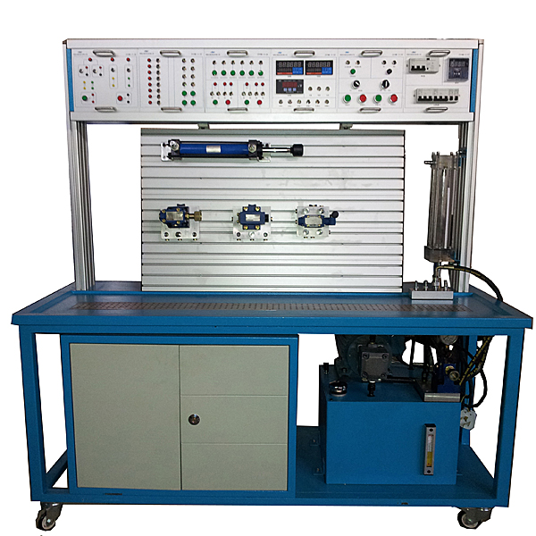
| 1 | Experimental bench | 1590´550´1680mm | 1 set | |
| 2 | Practical tr*ning screen | Aluminum alloy profile with "T" groove | 1 piece | Chinese teachings |
| 3 | Fixed vane pump | PV2R1-8R-F | 1 set | |
| 4 | variable vane pump |
Model: VP-15 Nominal displacement: 12L/min Rated pressure: 7Mpa |
1 set | |
| 5 | drive motor |
Rated power: 1.5KW, rated voltage: 380V |
1 set | |
| 6 | drive motor |
Rated power: 2.2KW, rated voltage: 380V |
1 set | |
| 7 | tank | 65L | 1 | Chinese teachings |
| 8 | oil filter | MF-04 | 1 | |
| 9 | Oil temperature and oil level gauge | YF-3” | 1 | |
| 10 | Double acting single rod cylinder |
HOB32*150LA pressure 10Mpa bore Ф32mm stroke 150mm |
2 pieces | |
| 11 | Unloading pressure regulating m*n valve |
YC-10 working pressure 0.7~7MPa |
1 item | |
| 12 | Pilot operated relief valve |
Y-10B pressure regulating range 0.5~6.3 MPa flow rate 10L/min |
1 item | |
| 13 | Pilot operated relief valve |
Y-25B pressure regulating range 0.5~6.3 MPa flow rate 25L/min |
1 item | |
| 14 | Direct acting relief valve |
DG-02 pressure 6.3 MPa flow 10L/min |
2 pieces | m*n valve |
| 15 | Remote pressure regulating valve |
YF-B8H1-S pressure regulating range 0.6-8MPa rated flow 2L/min |
2 pieces | |
| 16 | Pilot operated pressure reducing valve |
J-10B pressure regulating range 0.5-5MPa flow rate 10L/min |
1 item | |
| 17 | sequence valve |
X-25B pressure regulating range 0.5~6.3 MPa flow rate 25L/min |
2 pieces | |
| 18 | pressure relay | EYX15-5 | 1 item | |
| 19 | throttle valve |
L-10B working pressure 0.3~6.3 MPa flow 10L |
2 pieces | |
| 20 | Control Valve |
T-10B working pressure 0.5~6.3 MPa flow 10L |
2 pieces | |
| twenty one | One-way valve |
I-25B pressure 6.3MPa flow 25L/min |
3 pieces | |
| twenty two | Hydraulic control check valve |
IY-25B pressure 6.3MPa flow 25L/min |
1 item | |
| twenty three | Two-position two-way stroke reversing valve |
22C-25B pressure 6.3 MPa flow 25L/min |
1 item | |
| twenty four | Two-position two-way solenoid directional valve |
22E2-25BH pressure 6.3 MPa flow 25L/min |
1 item | |
| 25 | Two-position two-way solenoid directional valve |
22E2-25B pressure 6.3 MPa flow 25L/min |
2 pieces | |
| 26 | Two-position three-way solenoid directional valve |
23E2-25B pressure 6.3 MPa flow 25L/min |
1 item | |
| 27 | Two-position four-way solenoid directional valve |
24E2-25B pressure 6.3 MPa flow 25L/min |
2 pieces | |
| 28 | Three-position four-way solenoid directional valve |
34E2-25B pressure 6.3 MPa flow 25L/min |
2 pieces | |
| 29 |
34E2-25BH pressure 6.3 MPa flow 25L/min |
1 item | ||
| 30 |
DSG-01-3C4 pressure 6.3 MPa flow 25L/min |
1 item | ||
| 31 | Hydraulic control sequence valve |
XY-25B working pressure 0.5~6.3MPa flow rate 25L/min |
1 | |
| 32 | Annular gap test block |
FX pressure 1.5 MPa flow 10L/min |
1 item | |
| 33 | Slender hole test block |
XCH pressure 1.5 MPa flow 10L/min |
1 item | |
| 34 | Thin-walled small hole test block |
BBK pressure 1.5 MPa flow 10L/min |
1 item | |
| 35 | Oval gear flow meter |
LC-15 flow range 0.3-1.5m3/h nominal pressure 1.6MPa |
1 item | |
| 36 | Accumulator |
NXQA-0.63/ 10-LA volume 0.63L pressure 10MPa |
1 item | |
| 37 | ball valve |
YJZQ-H10N nominal pressure 20MPa |
1 item | |
| 38 | measuring cylinder |
YL 550ml |
1 item | |
| 39 | Quick connector |
KJ pressure 10 MPa |
40 sets | |
| 40 | Quick change connector (single head) |
DT pressure 10 MPa |
83 | |
| 41 | Threaded joint |
JT pressure 10 MPa |
30 pieces | For performance testing |
| 42 | Pipe str*ght connector |
ZT pressure 10 MPa |
16 | |
| 43 | Right angle joint for pipe |
GZ pressure 10 MPa |
16 | |
| 44 | Polyurethane high pressure oil pipe |
XPUΦ10-1 pressure 10 MPa |
16 roots | |
| 45 | tee joint |
SF3 pressure 10 MPa |
6 | Among them, there are 3 three-way connectors with meters |
| 46 | Four-way connector |
SF4 pressure 10 MPa |
2 | Chinese teachings |
| 47 | Quick change connection base plate |
KD 60mm´ 80mm |
40 | Chinese teachings |
| 48 | Oil manifold |
YLB pressure 10 MPa |
28 | Chinese teachings |
| 49 | Cylinder bottom plate | CT-DB | 2 | Chinese teachings |
| 50 | Top cylinder base | GZ | 1 | Chinese teachings |
| 51 | pressure gauge |
YTN150 0.4 level 1.6Mpa pressure gauge |
2 | Wuxi H*tian |
| 52 | pressure gauge |
YTN60 2.5 level 10mpa shock-resistant pressure gauge |
2 | Wuxi H*tian |
| 53 | pressure gauge |
YTN60 2.5 level 10 mpa pressure gauge |
3 | Wuxi H*tian |
| 54 | Programmable Controllers | FX1S-20MR-001 | 1 | Mitsubishi |
| 55 | PLC programming cable | SC-09 | 1 | Mitsubishi |
| 56 | relay | MY4NJ | 6 | Omron |
| 57 | Proximity switch | TX-SN5C-NPN | 4 | Kitaki, T*wan |
| 58 | Hall element | TX-12N4C-NPN | 1 | |
| 59 | Three-phase power meter | DK3-DV05 | 1 | Wenzhou Huaneng |
| 60 | Three-phase power transmitter | DT33S-W3.3KW | 1 | Wenzhou Huaneng |
| 61 | switching power supply | S200-24 | 1 | Changzhou, Jiangsu |
| 62 | switching power supply | 5V/1A | 1 | Changzhou, Jiangsu |
| 63 | transformer | TK500 | 1 | Changsha Lushan |
| 64 | *r switch | DZ47-16A | 1 | Chint Electrical Appliances |
| 65 | Insurance | RT18-32 | 3 | Chint Electrical Appliances |
| 66 | AC contactor | [JZC1-44/36V] | 7 | Chint Electrical Appliances |
| 67 | aviation plug | XS12/2P | 16 | M*feng instrument |
| 68 | aviation plug | XS12/3P | 11 | |
| 69 | aviation plug | XS12/4P | 8 | |
| 70 | aviation plug | XS16/4P | 1 | |
| 71 | red light button | ZB2-BWB41C | 1 | Schneider |
| 72 | Green light button | ZB2-BW31C | 8 | |
| 73 | red light button | ZB2-BWB42C | 4 | |
| 74 | Yellow light button | ZB2-BWB51C | 6 | |
| 75 | switch button | PBC[Y090]LYA7 | 1 | T*bo Electrical Appliances |
| 76 | Square button | LAS1J-22Z | 1 | red wave button |
| 77 | Voltmeter | 85C-V30V | 1 | Kedaly |
| 78 | Ammeter | 85C-A20A | 1 | Kedaly |
| 79 | indicator light | NHC-24V | 4 | Shangh* Fengshida |
| 80 | Terminals | 1534 | 2 | Chinese teachings |
| 81 | Digital display speed board | 1 | Chinese teachings | |
| 82 | digital temperature panel | 1 | Chinese teachings | |
| 83 | Signal conversion module | 1 | Chinese teachings | |
| 84 | PLC programming software | 1 set | Mitsubishi | |
| 85 | PLC Programming Manual ( electronic version) | 1 set | Mitsubishi | |
| 86 | Experimental Operation Manual | 1 volume | Chinese teachings | |
| 87 | sealing tape | 2 volumes | ||
| 88 | sealing ring | Group 1 | ||
| 89 | 6" adjustable wrench | 1 | ||
| 90 | open end wrench | 19-22 | 1 | |
| 91 | open end wrench | 22-24 | 1 | |
| 92 | open end wrench | 24-27 | 1 | |
| 93 | Allen wrench | 1.5-10mm | 1 | |
| 94 | Internal snap ring pliers | 6" | 1 | |
| 95 | External snap ring pliers | 6" | 1 | |
| 96 | screwdriver | +Word 150mm | 1 handful | |
| 97 | screwdriver | —Word 150mm | 1 handful | |
| 98 | Component storage basin | 3 | ||
| 99 | funnel | 1 | ||
| 100 | Hydraulic oil | 50kg |
 Wechat scan code follow us

24-hour hotline+86 18916464525

Phone18916464525
ADD:Factory 414, District A, No. 6, Chongnan Road, Songjiang Science and Technology Park, Shanghai ICP: Sitemap