Shanghai Daiyu Education Equipment Manufacturing Co., Ltd.
Language:

PRODUCT

PRODUCT CENTER

DYSF-01 Services proportional hydraulic comprehensive training device

Release time:2024-05-18 13:00viewed:times
  • DYSF-01 Services proportional hydraulic comprehensive training device
The servo proportional hydraulic comprehensive test bench device has a development test and analysis system, an intelligent data collection hydraulic test bench, and the intelligent hydraulic comprehensive test bench uses flow, pressure, power, rotational speed, displacement, time, temperature, computer man-machine screen - computer intelligence After a series of intelligent actions such as data collection, analysis, processing, and automatic production of reports and curves, various conventional experiments such as dynamic and static tests of hydraulic circuits, motors, and various valves and pumps are completed. Through the intelligent data collection hydraulic test bench intelligent hydraulic comprehensive experimental device experiment, the performance testing, intelligent control, remote control and communication technology of the hydraulic system and computer can be mastered and improved.
1. Composition of the experimental device
The experimental device consists of an experimental workbench, a hydraulic pump station, commonly used hydraulic components, an electrical control unit, and a data acquisition system.
1. Experimental workbench
The experimental workbench consists of an experimental installation panel (aluminum alloy profile), an experimental operating table, etc. The installation panel is an aluminum alloy profile structure with a "T" groove, which can conveniently and freely install hydraulic components and overlap the experimental circuit.
2. The auxiliary platform structure
is made of cold-rolled steel plate surface electrostatically sprayed. The table top is equipped with a "T" groove profile to facilitate the overlap of the hydraulic circuit during experiments. The inside of the platform is divided into two parts, one half of which is equipped with a "T" Half of the grooved aluminum alloy panel (the experiment is completed to facilitate the placement of hydraulic components) is an oil pipe bracket, and the bottom is equipped with a steel oil filter plate. There are four swivel casters at the bottom of the auxiliary platform for easy placement.
3. Commonly used hydraulic components
are m*nly domestic Rexroth series hydraulic valve components (Beijing Huade). For configuration det*ls, see the configuration list;
each hydraulic component is equipped with an oil path transition base plate, which can conveniently and arbitrarily place the hydraulic components on the experimental panel (aluminum alloy profile).
The oil circuit overlap uses open-close quick-change joints, which are easy to disconnect and connect without oil leakage.
4. Electrical control unit
Power supply: national standard power supply - AC220V (±5%), 50HZ, with short circuit protection, leakage protection, overload protection and other functions;
control voltage: safety control voltage - DC24V;
use environment requirements: can be used in Used under ambient temperature -10℃-+50℃;
programmable controller ( plc ): adopts Japanese Mitsubishi FX1N-24MR, I/O port 20 points, relay output form.
Leakage tripper, contactor, DC 24V power supply, solenoid valve output control port, proximity switch, connecting cable, socket, button, indicator light, etc.
5. Data acquisition system
This data acquisition system uses AD card as the data acquisition board; The configured sensors are all high-precision sensors with an accuracy level of 0.5 or above (can be configured with pressure sensor transmitter, turbine flow sensor, temperature transmitter, displacement sensor transmitter, power transmitter, torque speed sensor Transmitter, etc.), each sensor transmitter has a standard signal output, and the external connecting cables of the sensors use special cables with good shielding effects to ensure the accuracy of data collection. The data acquisition software collects data from the output signals of this series of sensors, draws relevant curves in real time, generates real-time data reports, draws dynamic curves on any XY axis, and has curve printing functions, data report saving and printing functions, and parameters of each sensor. Setting functions and so on. Realize computer intelligent data collection, analysis, processing, digital display, automatic curve generation and real-time monitoring functions, in line with the future development trend of hydraulic control. Electricity safety and electric shock first *d simulation teaching software (copyright certificate and demonstration are provided when bidding) The software uses a virtual screen that combines two-dimensional and three-dimensional to teach students the safety of electricity and first *d methods. The software has single-phase electric shock and two-phase electric shock. , explanation and teaching on the principles of step electric shock, low voltage electric shock first *d, high voltage electric shock first *d, artificial respiration rescue method, hand-holding breathing rescue method, chest heart compression rescue method, etc. Single-phase electric shock is divided into rep*ring live disconnection, rep*ring socket electric shock, and outdoor electric shock. W*t for principle demonstration. The teaching of low-voltage electric shock and high-voltage electric shock m*nly expl*ns and demonstrates to students how to rescue people who are suffering from low-voltage electric shock or high-voltage electric shock. Artificial respiration rescue method, hand-holding breathing rescue method, and chest cardiac compression rescue method are demonstrated using 3D virtual simulation technology. After rendering and Polish it to make the model look like the real part and look realistic. Through practical tr*ning, students can be educated on the safe use of electricity in the tr*ning room, improve students' safety awareness, and enable students to learn some self-rescue methods, so that students can take cert*n safety measures to protect themselves when encountering danger, and become familiar with various Causes of electrical accidents and practical measures to deal with them to reduce the occurrence of electrical accidents. plc programmable design and control virtual simulation software (copyright certificate and demonstration provided when bidding): This software can be programmed through the software's built-in PLC program programming interface and can be written into a virtual PLC to control the 3D simulation model. It can simulate the start, stop, forward and reverse rotation of the conveyor belt, two-channel sorting of materials of different sizes, material supply control, material detection, material processing, mechanical control, traffic light control, three-channel sorting of materials of different sizes, elevator control, and materials of different sizes. There are no less than 20 3D simulation models including forward and reverse transport to different warehouses via conveyor belts, defective product sorting, automatic door control, stage lifting and curt*n control, etc. The software can also monitor the virtual PLC input/output status and use the reset function to reset a component when it gets stuck. The software has a step-by-step teaching function, teaching from easy to difficult.
6. Virtual simulation tr*ning software.
Hydraulic and pneumatic transmission design and control virtual simulation software.
This software is developed based on unity3d. The software adopts the form of three-dimensional roaming. Movement can be controlled by the keyboard and the lens direction can be controlled by the mouse. The interface has homepage, help, full screen, and components. Cognition, loop construction, key component testing, typical system testing interface.
1. Component identification adopts the form of automatic playback, which introduces the m*lbox, liquid level gauge, oil pump unit on the equipment (the pop-up hydraulic symbols, principles and introduction are introduced here, click OK to enter the next introduction), valve frame, and pressure gauge. , sensors, etc.
2. The disassembly and assembly of components is divided into learning mode and assessment mode. There are built-in electromagnetic reversing valves, plate relief valves, plunger pumps, filter valves, and electro-hydraulic servo valves. In the learning mode, the disassembly sequence is prompted and highlighted. There are no prompts for disassembly and installation in assessment mode. If the disassembly and assembly sequence is wrong, the next step of disassembly and assembly will no longer be possible. The toolbar is equipped with draggable seals, pumps, valves, oil filters, hex wrenches, pipe wrenches, adjustable wrenches, dead wrenches, and M5 screws.
3. The hydraulic components are equipped with one-way valve (hydraulic control, poppet valve core, ball valve core), m*n structure of the reversing valve (O type, Y type, H type), hydraulic cylinder (assembled plunger, double-acting single outlet rod) , double-action double-output rod, single-action double-output rod, single-action single-output rod), etc. Each construction experiment adopts a graphical method and is constructed by dragging the set graphics. In the graphics library There are confusing graphics.
4. Hydraulic selection is based on the hydraulic schematic diagram, and then selects the nominal displacement of the pump (12 items, including 11 confusing items) and pressure level (5 items, including 4 confusing items), and the selection of the solenoid relief valve (3 specifications, 3 pressure levels, and 3 flow levels, all of which have confusing items), oil filter selection (multiple choices include confusing items), servo valve selection (multiple choices include confusing items), and the wrong selection system will Automatically prompt the correct answer. After selecting, drag the corresponding tool to the highlighted area according to the prompt.
5. Circuit inspection is done by selecting the correct accessories, including the selection of sealing rings, checking valve switches, etc. Then proceed to the next step to turn on the machine. Follow the prompts to turn on the machine. After turning on the machine, enter the monitoring interface. Turn on the equipment one by one according to the prompts. The prompts are in the form of text and button highlighting.
6. Hydraulic cylinder pressure test Enter the experiment through the test button on the background interface and gradually analyze To start friction test, start friction force, parameter setting, start test, draw curve, stop test.
7. Typical system tests are divided into trial operation, stage response test and frequency response test. The above tests are all conducted through the background monitoring interface.
8. The software must be able to rotate, zoom in and out in all directions to view its det*ls. And the same platform as a whole cannot be displayed as separate resources.
Microcontroller , PLC programmable design and control virtual simulation software.
This software is developed based on unity3d. It has built-in task books and experimental prompts. It adopts the form of three-dimensional roaming. Movement can be controlled by the keyboard, the direction of the lens can be controlled by the mouse, and the distance of the picture can be controlled by the mouse wheel, which can be 360 ​​degrees. Rotating, three-dimensional wall p*nted with electrical diagrams.
1. Equipment component assembly: Follow the highlighted prompts to find the component control rack. You can drag components from the component library according to the electrical component layout diagram and place them on the component control rack. The component library is equipped with control panels, switching power supplies, micro relays, and PLCs. , frequency converter, stepper motor , AC motor, servo motor, servo driver, stepper driver, interface board, operation panel, circuit breaker, servo motor interface, digital display voltmeter, there will be a prompt when the selection is wrong.
2. Technical indicator measurement: Select a multimeter to check the servo motor connection cable and the servo driver with BOP panel. Adjust the left and right buttons to the ohm level, drag the black and red test leads and insert them into the R, S, T, U, V, W, and ground phases respectively for testing. For resistance value, according to the highlighted prompt, find the power switch in the scene, drag the pen or multimeter to measure whether the power is on.
3) Electrical component connection: According to the electrical wiring diagram, connect the power line and control line, highlight the interface, connect the driver, interface board, power line, servo motor, encoder, PLC, and relay in order, and turn on the m*n power supply After turning on the switch, servo power switch, and faulty circuit switch, a fault code will be prompted, and you can select the cause of the fault from three items.
4) Parameter adjustment test: Turn on the power to adjust the speed, set the driver parameters according to the requirements of the mission statement, perform inching control/analog speed adjustment/multi-stage speed control, and observe the three-dimensional servo motor motion control. Select any of the 6 PLC programs and then adjust the servo drive analog speed. The PLC parameters are adjustable. Set the drive parameters and enter the three-dimensional servo motor motion control interface and electrical display interface. The operation panel is equipped with servo start, low speed, medium Speed, high speed, servo stop, torque limit, abnormal reset, forward/reverse rotation selection, 0-10 sliding control (the electrical panel displays the value in real time).
5) Inspect the three-dimensional virtual simulation machine of the servo system mask machine, observe its structure, inject fault points, select multiple fault causes, and locate faults. Connect the fault causes with the corresponding detection and positioning methods, and troubleshoot after selecting the correct ones. Connect the cause of the f*lure with the corresponding solution.
6) Control process plan, optional single machine mode and online mode of inching control/analog speed regulation/multi-stage speed regulation control, call up the control panel, display the operation of 3 production lines, perform real-time control, optional inching, low and medium High speed, start and stop control, adjustable speed. According to the control plan, the system automatically determines the performance of the production line and submits a disclosure record.
2. Technical parameters:
1) Input power supply voltage: three-wire and five-wire AC380V±10%50HZ;
2) DC voltage of modules and components: DC24V, 4.5A, with automatic short-circuit protection function;
3) Control voltage: safety control voltage - DC24V ;
4) Usage environment: temperature -10℃~+40℃, relative humidity <85% (25℃), altitude <4000m (dust-proof and moisture-proof);
5) Product size: length × width × height = 2450mm*700mm*1850mm;
6 ) Total power: <=5KW;
7) Rated pressure: <=7Mpa;
8) Net weight: about 295kg;
9) Hydraulic pump unit components: (Double pump unit)
System rated working pressure: 6Mpa. (Maximum up to 7Mpa)
(1) Motor-pump device (2 units)
A. Fixed vane pump: nominal displacement 12mL/r, volumetric efficiency 90%;
fixed vane pump drive motor: three-phase AC voltage, power 2.2KW, Rotating speed 1450r/min;
equipped with pilot relief valve.
B. Variable vane pump: low-pressure variable vane pump, nominal displacement 12mL/r, pressure adjustment range 4~7Mpa;
variable vane pump motor: three-phase AC voltage, power 1.5KW, speed 1450r/min;
(2) Fuel tank: nominal Volume 60L; equipped with liquid level and oil temperature indicators, oil suction and oil return filters, safety valves, etc.;
(3) High-quality hydraulic oil: PetroChina 32# anti-wear hydraulic oil
(4) Air cooler: pressure 0- 1.6Mpa; flow rate: 40L;
3. M*n features:
1. Modular structure design, equipped with an installed bottom plate, which can be freely mounted on a general aluminum alloy profile plate during experiments, and the circuit assembly operation is simple and convenient.
2. It has strong scalability: due to the modular design, the component modules have independent functions and are easy to expand and upgrade.
3. The system all uses standard industrial hydraulic components, which is safe, reliable and close to reality.
4. The fast and reliable connection method and special sealing interface ensure that the experimental assembly is easy and fast, and the disassembly does not leak oil and is clean.
5. Intelligent experimental data collection and processing method. On-site instrument testing and analysis of pressure, flow, displacement, power, temperature, etc. can be performed on hydraulic circuits. Through corresponding interfaces and testing software, hydraulic test data can be analyzed on the computer.
6. Programmable controller (PLC) electrical control, electromechanical and hydraulic integrated control experimental form.
7. The electrical circuit uses safety wires, 24VDC safety voltage, and is equipped with a current leakage protection device.
8. The motor-pump is integrated, with stable operation and low noise.
4. Experimental projects:
1) Performance testing of commonly used hydraulic components (static and dynamic):
1. Characteristic testing of hydraulic pumps;
2. Characteristic testing of the relief valve;
3. Characteristic testing of throttle valve;
4. Characteristic testing of speed control valve;
5. Characteristic testing of pressure reducing valve;
6. Characteristic testing of sequence valves;
7. Characteristic testing of hydraulic control check valve;
8. Characteristic test of electromagnetic reversing valve;
2) Basic circuit experiment of hydraulic transmission:
1. The oil inlet throttling and speed regulating circuit using a throttle valve;
2. The oil return throttle speed regulating circuit using the throttle valve;
3. A bypass throttling and speed regulating circuit using a throttle valve;
4. The oil inlet throttling speed control circuit using the speed control valve;
5. The oil return throttling speed control circuit using the speed control valve;
6. Using bypass throttling and speed regulating circuit of speed regulating valve;
7. Simple pressure setting loop;
8. A pressure regulating circuit with variable pump and bypass orifice throttling;
9. A pressure regulating circuit using multiple relief valves (two-stage pressure regulating circuit);
10. Pressure reducing circuit using pressure reducing valve;
11. Use the speed of the stroke valve to switch the circuit;
12. Speed ​​switching circuit of speed regulating valve in series;
13. Speed ​​switching circuit for speed control valves connected in parallel;
14. Unloading circuit using three-position directional valve;
15. Unloading circuit using pilot relief valve;
16. Sequential action circuit using sequence valve;
17. Adopt the sequential action circuit of electrical travel switch;
18. Adopt the sequential action circuit of pressure relay;
19. A locking (balanced) circuit using a hydraulically controlled one-way valve;
20. Balance circuit using sequence valve;
21. Accumulator applications.
3) Expanded hydraulic circuit experiments designed and assembled by students themselves; (can be expanded to hundreds of experiments)
4) Programmable controller (PLC) electrical control experiment
1. Learning of PLC instruction programming and ladder diagram programming;
2. Learning and using PLC programming software;
3. Communication between PLC and computer, online debugging and monitoring;
4. Optimal control of hydraulic transmission by PLC;
5) Data acquisition system experiment: It can carry out functional experiments such as experimental data collection, analysis, processing, real-time display, and automatic generation of experimental curves.
6) Proportional hydraulic type:
1. Performance test of proportional valve:
1) Control characteristic test of proportional relief valve;
2) Load characteristic test of proportional relief valve;
3) Dynamic characteristic test of proportional relief valve;
4) Proportional Control characteristic test of directional valve;
5) Throttle characteristic test of proportional directional valve;
6) Dynamic characteristic test of proportional directional valve.
2. Experiments related to hydraulic proportional control:
1) Pressure stabilization control loop experiment of electromagnetic proportional relief valve;
2) Electromagnetic proportional relief valve pressure control system;
3) Reversing circuit of electromagnetic proportional directional valve;
4) Electromagnetic proportional directional valve Speed ​​control loop with cut-off characteristics;
5) Hydraulic cylinder position control experiment of proportional control system;
6) Simple hydraulic closed-loop control experiment of proportional system, etc.
3. Design experiments of computer-controlled electro-hydraulic proportional position system
1) Proportional valve control performance experiment;
2) Pressure characteristics of proportional relief valve;
3) Proportional relief valve pressure characteristics testing device;
4) Proportional relief valve input Physical meaning and test methods of output characteristics;
5) Pressure regulating characteristics and testing methods of proportional relief valve;
6) Dynamic characteristics experiment of proportional relief valve;
7) Dynamic characteristics testing device of proportional relief valve;
8) Test of pressure step response characteristic curve of proportional relief valve Method;
9) The physical meaning and calculation method of each parameter of the dynamic characteristics of the proportional relief valve;
10) The flow
characteristic experiment of the electromagnetic proportional directional valve 11) The flow characteristic testing device of the electromagnetic proportional directional valve;
12) The input and output of the electromagnetic proportional directional valve controller The physical meaning and testing methods of the characteristics;
13) The flow characteristics and testing methods of the electromagnetic proportional directional valve;
14) The dynamic performance experiment of the electromagnetic proportional directional valve;
15) The dynamic characteristics device of the electromagnetic proportional directional valve;
16) The characteristics of the electromagnetic proportional directional valve Test method of flow step response characteristic curve;
17) Dynamic characteristics and parameter physical meaning of electromagnetic proportional directional valve and test method;
18) Performance experiment of electro-hydraulic proportional force control system;
19) Composition and operation of electro-hydraulic proportional force control system Principles and correction methods;
20) The role of computers in electro-hydraulic proportional force control systems;
21) System dynamic analysis principles and time dom*n parameter testing methods;
22) The impact of digital PID controller structural parameters on system dynamic performance;
23) Electrical Performance experiments of hydraulic proportional position control systems;
24) The role of computers in electro-hydraulic proportional position control systems;
25) System dynamic analysis principles and time dom*n parameter testing methods;
26) Commonly used PID controller types and algorithms;
27) Digital PID The influence of controller structure
parameters on the dynamic performance of the system;
4. Servo valve performance test
1) Flow characteristic experiment of servo reversing valve;
2) Servo reversing valve flow characteristic testing device;
3) Input of servo reversing valve controller The physical meaning and testing methods of the output characteristics;
4) The flow characteristics and testing methods of the servo reversing valve;
5) The performance experiment of the force control system of the
servo reversing valve; 6) The composition and working principle of the force control system of the servo reversing valve and correction methods;
7) The role of computers in the force control system of servo reversing valves;
8) System dynamic analysis principles and time dom*n parameter testing methods;
9) Commonly used PID controller types and algorithms;
10) Digital PID controller structure The influence of parameters on the dynamic performance of the system;
11) Closed-loop force control system;
13) Performance experiment
of the position control system of the servo reversing valve; 14) The composition, working principle and correction method of the position control system of the servo reversing valve;
15) The role of the computer in the position control system of the servo reversing valve;
16) System dynamic analysis principles and time dom*n parameter testing methods;
17) Commonly used PID controller types and algorithms;
18) The impact of digital PID controller structural parameters on system dynamic performance Impact;
19) Electro-hydraulic proportional hydraulic motor speed control experiment (customer optional);
20) Electro-hydraulic proportional speed regulating valve flow characteristics performance experiment;
21) Electro-hydraulic proportional speed regulating valve flow characteristics testing device;
22) Electro-hydraulic proportional regulating valve The physical meaning and test methods of the input and output characteristics of the speed valve controller;
23) The flow characteristics and test methods of the electro-hydraulic proportional
speed valve 24) The dynamic performance experiment of the electro-hydraulic
proportional speed valve; 25) The electro-hydraulic proportional speed valve Dynamic characteristics testing device;
26) Test method for the flow step response characteristic curve of the electro-
hydraulic proportional speed control valve; 27) Physical meaning and calculation method of each parameter of the dynamic characteristics of the electro-hydraulic proportional speed control valve
28) Performance experiment of the electro-hydraulic proportional speed control system ;
29) The composition, working principle and correction method of the electro-hydraulic proportional speed control system;
30) The role of the computer in the electro-hydraulic proportional speed control system;
31) System dynamic analysis principles and time dom*n parameter testing methods
32) Master common PID controllers Type and algorithm;
33) In-depth understanding of the impact of digital PID control parameters on the dynamic performance of the system;
configuration list:

serial number Name Specifications and models quantity Remark
Experimental console
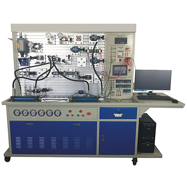
Experimental bench Welded steel structure 1 set Chinese teachings
Auxiliary experimental bench Steel structure and aluminum profiles overlapped 1 set Chinese teachings
Universal wheel With self-locking function; roller bearing 4 Install the bottom of the experimental bench
foot pads adjustable fixed 4 Install the bottom of the experimental bench
Hydraulic power station
Special pump station control system
(1 set)
Open with leakage protection 1 CHNT
AC contactor   2 CHNT
220V relay 2 Omron
emergency button 1 Chinese teachings
Button (red, green) 2 each Chinese teachings
10  indicator light 2 sucks Chinese teachings
11  emergency button 1 each Chinese teachings
12P Fixed vane pump + drive motor Rated displacement: 12ml/r
Rated pressure: 21MPa
Rated power: 2.2kw
Rated voltage: AC380V
  Chinese teachings
13  Variable vane pump + drive motor Rated displacement: 6.67ml/r
Rated pressure: 6.3MPa
Rated power: 1.5kw
Rated voltage: AC380V
1 set Chinese teachings
14  Accumulator NXQ-0.6L 1 set K*hong Hydraulic
15  tank Rated volume 60L 1 Chinese teachings
16  *r filter HS-1163 1 Densheng Hydraulic
17  oil suction filter MF-04 1 Densheng Hydraulic
18  Pilot operated relief valve DB10 2 SUPER
19  Pilot operated relief valve block   2 sets Chinese teachings
20  Oil temperature and oil level gauge LS-3 1 Densheng Hydraulic
twenty one  One-way valve S10A12B/ 2 Huade Hydraulic
twenty two  *r cooler AW0607-CA1∮220V 1 Hengchang
twenty three  pressure gauge YN-60 0-10MPa 2 Feitian Hydraulic
24 Department System auxiliary pressure gauge YN-60 0-10MPa 4 Feitian Hydraulic
25  oil pipe 1.5 m 2 pieces Chinese teachings
Hydraulic accessories
26  Double acting hydraulic cylinder assembly Component model: MOB-50*200-LB
Maximum stroke: 200mm Bore size 50
2 TIANYU
27  Throttle valve stop valve assembly Component model: DV12-1-10B/ 2 Huade Hydraulic
28  One-way valve assembly Component model: S10A02B/ 2 Huade Hydraulic
29  Hydraulic control check valve assembly Component model: SV10PB1-30B/
Component model: FQ-SV10-3F
1 Huade Hydraulic
30  Relief valve (direct-acting) components Component model: DBDH6P10B/100
Component model: FQ-DH6P-2F
2 Huade Hydraulic
31  Relief valve (pilot type) components Component model: DB10-1-30B/315
Component model: FQ-DB10-3F
1 Huade Hydraulic
32  Sequence valve components Component model: DZ10-1-30B/210YM
Component model: FQ-DZ6-3F
2 Huade Hydraulic
33  One-way speed regulating valve assembly Component model: 2FRM5-31B/15QB
Component model: FQ-2FRM5-2F
1 Huade Hydraulic
34  Pressure reducing valve assembly Component model: DR10-1-30B/100Y
Component model: FQ- DR10-2F
1 Huade Hydraulic
35  Two-position three-way electromagnetic reversing valve assembly Component model: 3WE6A61B/CG24N9Z5L
Component model: FQ-3WE6A-3F
1 Huade Hydraulic
36  Two-position four-way solenoid valve assembly Component model: 4WE6C61B/CG24N9Z5L
Component model: FQ-4WE6C-3F
2 Huade Hydraulic
37  Three-position four-way solenoid directional valve (O) components Component model: 4WE6E61B/CG24N9Z5L
Component model: FQ-4WE6E-3F
1 Huade Hydraulic
38  Three-position four-way solenoid directional valve (M) components Component model: 4WE6G61B/CG24N9Z5L
Component model: FQ-4WE6G-3F
1 Huade Hydraulic
39  Three-position four-way solenoid directional valve (Y) components Component model: 4WE6J61B/CG24N9Z5L
Component model: FQ-4WE6J61B -3F
1 Huade Hydraulic
40  Two-position four-way manual reversing valve assembly Component model: 4WMM6E50B/
Component model: FQ-4WMM6E-3F
1 Huade Hydraulic
41  Pressure relay components Component model: HED80A1X/100Z14KW
Component model: FQ-HED8-1M
1 Huade Hydraulic
42  Proportional relief valve Component model: DBE10-30B/100YM
Component model: FQ- DBE10-1M
1 Beijing Huade Hydraulic
43  amplifier Component model: VT-200S40
Component model: FQ- VT-200S40-1M
1 Beijing Huade Hydraulic
44  Solenoid proportional directional valve Component model: 4WRE6E16-10B/24Z4M (with feedback)
Component model: FQ-4WRE6E16-10B/24Z4M
1 Beijing Huade Hydraulic
45  amplifier Component model: VT-5005
Component model: FQ- VT-5005
1 Beijing Huade Hydraulic
46  Servo hydraulic valve FF-102 1 AVIC
609 Research Institute
47  Servo hydraulic cylinder (with displacement sensor) Component model: Φ50×36×200 1 Wuxi
48  Displacement sensing transmitter Component model: 0-200mm 1 Built into servo cylinder
49  pressure line filter Component model: ZU-E25×10S 2 Changzhou
50  Four-way components Component model: FQ-4T-3F 6 Chinese teachings
51  Glycerin pressure gauge components Component model: FQ-10MP a-1F-1M 4 relda
52  High pressure oil hose assembly Component model 10-1-25.6MP a-2M-0.7 10 sticks Chinese teachings
53  High pressure oil hose assembly Component model 10-1-25.6MP a-2M-1.0 15 pieces Chinese teachings
54  Hydraulic valve transition base plate A special base plate for hydraulic valves is installed on the valve 20 yuan Chinese teachings
55  Quick change connector male connector Open and close hydraulic quick connector 90 pieces Wellcome
56  Quick change connector female connector Open and close hydraulic quick connector 56 Wellcome
57  Oil inlet and oil separation components Component model: 4P-4F 2 sets Chinese teachings
58  Oil return and oil separation components Component model: 4T-4F 1 set Chinese teachings
59  Hydraulic oil 32# anti-wear hydraulic oil 60 liters PetroChina
data collection system
60  computer With PCI slot, COM interface, nationwide warranty 1 set Lenovo brand machine
61  monitor 19' LCD monitor 1 set Lenovo brand machine
62  Data acquisition card SJJ 1 piece Chinese teachings
63  Data acquisition cable   1 Chinese teachings
64  Pressure Sensor KE-240001/100BG5W 4-20mA signal output 2 Chinese teachings
65  Flow Sensors LWGY-6 4-20mA signal output 1 Chinese teachings
66  Temperature Sensor Pt100 4-20mA signal output 1 Chinese teachings
67  Motion detector NS-WY03 0-300mm 4-20mA signal output 1 Chinese teachings
68  connecting cables 2 meters 1 Chinese teachings
control Panel
69  PLC input and output module Component model: FQ-PLC-IN/OUT
PLC: Mitsubishi FX1S-20MR 20 points
1 set Mitsubishi
70  Data acquisition module Component model: FQ-PCI-2W
Acquisition card: PCI-1713U
32 single-ended or 16 differential analog inputs, or combined input mode, 12-bit A/D conversion resolution, A/D converter sampling rate up to 100KS/s, on-card 4096 sample FIFO buffer, 2,500VDC isolation protection, programmable g*n for each input channel, supports software, internal timer trigger or external trigger sampling mode
1 set Chinese teachings
71  Intelligent display module Component model: FQ-ZN-50W
pressure display instrument,
flow display instrument,
displacement display instrument,
temperature display instrument
1 set Chinese teachings
appendix
72  Proximity switch DC24V two-wire system 4 Industrial parts
73  Special bracket for proximity switch Aluminum profiles, professional mold making 4 sets Chinese teachings
74  PLC programming cable   1 Mitsubishi
75  Power strip AC250V three holes 1 bull
76  Product manual Instructions, instructions 1 volume Chinese teachings
77  Hydraulic Atlas   1 volume Chinese teachings
78  Essential tools for equipment m*ntenance 1 set of Allen wrenches (nine-piece set), 1 screwdriver (nine-piece set), 2 12-inch adjustable wrenches, 1 needle-nose pliers 1 set Standard Parts
 

DAIYUWechat scan code follow us

  • 24-hour hotline+86 18916464525

  • Phone18916464525

 ADD:Factory 414, District A, No. 6, Chongnan Road, Songjiang Science and Technology Park, Shanghai ICP: Sitemap