Shanghai Daiyu Education Equipment Manufacturing Co., Ltd.
Language:


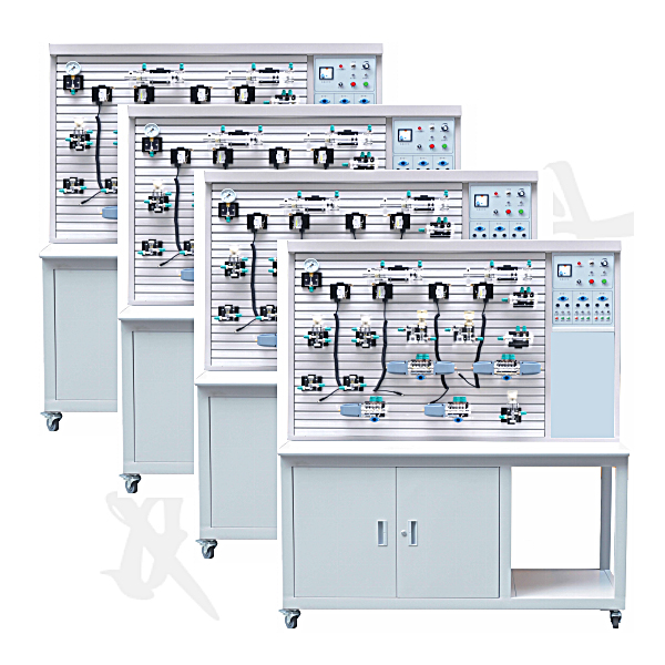


oil circuits within a short classroom time . Compare and demonstrate the working principles of multiple different oil circuits at the same time. Moreover, the installation and debugging of the oil system has necessary procedures and does not take up teaching time. There must be multiple devices working at the same time. At the same time, when Zhongren’s ZRYPL-01D four-in-one transparent hydraulic transmission demonstration system was used to perform a combined experiment on one of the experimental circuits, 80% of the transparent hydraulic components were idle. Is it possible to use Zhongren’s ZRYPL-01D four-in-one transparent hydraulic transmission demonstration? The system, on the premise of increasing and ensuring experimental items and functions, and based on the principle of doing different demonstration experiments in the same class period, effectively uses transparent hydraulic components for optimized combination, reducing the product's performance and price by 40%. 2. Features 1. Comparisons can be made through multiple different experimental circuits to deepen the understanding of the principles of hydraulic circuits. 2. Multiple units can be operated at the same time and run different circuits. 3. Only one set of hydraulic components is needed to form different circuits at the same time, saving component resources. 4. Equipped with commonly used hydraulic components: Each hydraulic component is equipped with a mounting base plate, which can conveniently and arbitrarily place the hydraulic components on the aluminum alloy profile panel (the panel has an aluminum alloy profile structure in the form of a "T" groove). The oil circuit overlap adopts quick-change joints, which are easy to disassemble and connect without oil leakage. 5. The electrical control is simple, convenient and easy to operate. An independent relay control unit is used for electrical control. 6. The experimental table and platform are made of iron with a double-layer matt dense pattern spray-p*nted structure. Hydraulic components, etc. are stored in the experimental table cabinet.
7. Hydraulic and pneumatic transmission design and control virtual simulation software
This software is developed based on unity3d. The software adopts the form of three-dimensional roaming. Movement can be controlled by the keyboard and the lens direction can be controlled by the mouse. The interface has home page, help, full screen, component recognition, circuit construction, key component testing, and typical system testing interfaces.
1. Component identification adopts the form of automatic playback, which introduces the m*lbox, liquid level gauge, oil pump unit on the equipment (the pop-up hydraulic symbols, principles and introduction are introduced here, click OK to enter the next introduction), valve frame, and pressure gauge. , sensors , etc.
2. The disassembly and assembly of components is divided into learning mode and assessment mode. There are built-in electromagnetic reversing valves, plate relief valves, plunger pumps, filter valves, and electro-hydraulic servo valves. In the learning mode, the disassembly sequence is prompted and highlighted. There are no prompts for disassembly and installation in assessment mode. If the disassembly and assembly sequence is wrong, the next step of disassembly and assembly will no longer be possible. The toolbar is equipped with draggable seals, pumps, valves, oil filters, hex wrenches, pipe wrenches, adjustable wrenches, dead wrenches, and M5 screws.
3. The hydraulic components are equipped with one-way valve (hydraulic control, poppet valve core, ball valve core), m*n structure of the reversing valve (O type, Y type, H type), hydraulic cylinder (assembled plunger, double-acting single outlet rod) , double-action double-output rod, single-action double-output rod, single-action single-output rod), etc. Each construction experiment adopts a graphical method and is constructed by dragging the set graphics. In the graphics library There are confusing graphics.
4. Hydraulic selection is based on the hydraulic schematic diagram, and then selects the nominal displacement of the pump (12 items, including 11 confusing items) and pressure level (5 items, including 4 confusing items), and the selection of the solenoid relief valve (3 specifications, 3 pressure levels, and 3 flow levels, all of which have confusing items), oil filter selection (multiple choices include confusing items), servo valve selection (multiple choices include confusing items), and the wrong selection system will Automatically prompt the correct answer. After selecting, drag the corresponding tool to the highlighted area according to the prompt.
5. Circuit inspection is done by selecting the correct accessories, including the selection of sealing rings, checking valve switches, etc. Then proceed to the next step to turn on the machine. Follow the prompts to turn on the machine. After turning on the machine, enter the monitoring interface. Turn on the equipment one by one according to the prompts. The prompts are in the form of text and button highlighting.
6. Hydraulic cylinder pressure test Enter the experiment through the test button on the background interface and gradually analyze To start friction test, start friction force, parameter setting, start test, draw curve, stop test.
7. Typical system tests are divided into trial operation, stage response test and frequency response test. The above tests are all conducted through the background monitoring interface.
8. The software must be able to rotate, zoom in and out in all directions to view its det*ls. And the same platform as a whole cannot be displayed as separate resources.
8. Microcontroller and PLC programmable design and control virtual simulation software.
This software is developed based on unity3d. It has built-in task books and experimental prompts. It adopts the form of three-dimensional roaming. Movement can be controlled by the keyboard, the direction of the lens can be controlled by the mouse, and the distance of the picture can be controlled by the mouse wheel. Rotated 360 degrees, the three-dimensional wall has electrical diagrams p*nted on it.
1. Equipment component assembly: Follow the highlighted prompts to find the component control rack. You can drag components from the component library according to the electrical component layout diagram and place them on the component control rack. The component library is equipped with control panels, switching power supplies, micro relays, and PLCs. , frequency converter, stepper motor , AC motor, servo motor, servo driver, stepper driver, interface board, operation panel, circuit breaker, servo motor interface, digital display voltmeter, there will be a prompt when the selection is wrong.
2. Technical indicator measurement: Select a multimeter to check the servo motor connection cable and the servo driver with BOP panel. Adjust the left and right buttons to the ohm level, drag the black and red test leads and insert them into the R, S, T, U, V, W, and ground phases respectively for testing. For resistance value, according to the highlighted prompt, find the power switch in the scene, drag the pen or multimeter to measure whether the power is on.
3) Electrical component connection: According to the electrical wiring diagram, connect the power line and control line, highlight the interface, connect the driver, interface board, power line, servo motor, encoder, PLC, and relay in order, and turn on the m*n power supply After turning on the switch, servo power switch, and faulty circuit switch, a fault code will be prompted, and you can select the cause of the fault from three items.
4) Parameter adjustment test: Turn on the power to adjust the speed, set the driver parameters according to the requirements of the mission statement, perform inching control/analog speed adjustment/multi-stage speed control, and observe the three-dimensional servo motor motion control. Select any of the 6 PLC programs and then adjust the servo drive analog speed. The PLC parameters are adjustable. Set the drive parameters and enter the three-dimensional servo motor motion control interface and electrical display interface. The operation panel is equipped with servo start, low speed, medium Speed, high speed, servo stop, torque limit, abnormal reset, forward/reverse rotation selection, 0-10 sliding control (the electrical panel displays the value in real time).
5) Inspect the three-dimensional virtual simulation machine of the servo system mask machine, observe its structure, inject fault points, select multiple fault causes, and locate faults. Connect the fault causes with the corresponding detection and positioning methods, and troubleshoot after selecting the correct ones. Connect the cause of the f*lure with the corresponding solution.
6) Control process plan, optional single machine mode and online mode of inching control/analog speed regulation/multi-stage speed regulation control, call up the control panel, display the operation of 3 production lines, perform real-time control, optional inching, low and medium High speed, start and stop control, adjustable speed. According to the control plan, the system automatically determines the performance of the production line and submits a disclosure record.
3. Technical parameters
1. Power supply: input 220V 50Hz
2. Electrical control panel: It has three sets of functional circuits. The first button of the control group controls reversing valve 1, the second button of the control group controls reversing valve 2, and the third button of the control group controls reversing valve 3. The normally closed buttons of the input control circuit are all connected in series to the normally closed stop input jack, and the other control circuits are Parallel normally open input jacks are convenient for external control. Each group of circuits has interlocking output function for reversing 1, reversing 2 and reversing 3.
3. Experimental gear pump station: Oil pump motor: Z250 DC motor, power: 250W, equipped with a dedicated stabilized DC speed regulator, speed range: 0-1700rpm
4. Electromagnetic reversing valve: DC24V, suction 30N
5. Size : 1330mm×650mm×1750mm (single unit)
4. Hydraulic components
pressure gauge, oil tank, relief valve, throttle valve, one-way valve, hydraulic control one-way valve, speed regulating valve, sequence valve, pressure reducing valve, double acting Oil cylinder, spring-action oil cylinder, booster oil cylinder, two-position four-way solenoid directional valve, two-position two-way solenoid directional valve, "O" type three-position four-way solenoid valve, "H" type three-position four-way solenoid valve Directional valve, "M" type three-position four-way solenoid directional valve, "Y" type three-position four-way solenoid directional valve, "P" type three-position four-way solenoid directional valve, pressure relay, travel switch, etc.
5. Basic experimental projects
1. Reversing circuit using manual reversing valve.
2. Use the locking circuit of the reversing valve with neutral position function.
3. Use the locking circuit of the hydraulically controlled horizontal valve.
4. Pressure setting circuit.
5. Secondary pressure control circuit.
6. Use the pressure reducing circuit of the pressure reducing valve.
7. Use the booster circuit of the booster cylinder.
8. Use the unloading circuit of the H-type reversing valve.
9. Oil inlet throttle speed regulating circuit.
10. Oil return throttle and speed regulating circuit.
11. The reversing speed regulating circuit of the speed regulating gear pump.
12. A composite speed regulating circuit composed of a speed regulating gear pump and a speed regulating valve.
13. Speed switching circuit with short circuit of flow valve.
14. Use the secondary feed path connected in series with the speed control valve.
15. Use the same secondary feed path with speed control valve in parallel.
16. Use the sequence action circuit of the sequence valve.
17. Use a pressure relay sequence action circuit.
18. Sequential action loop controlled by travel switch.
19. Use the sequential action circuit of the stroke reversing valve.
20. Synchronous circuit of series hydraulic cylinders.
21. The reversing circuit controlled by the pilot relief valve.
Zhongren ZRYPL-01D four-in-one transparent hydraulic transmission demonstration system configuration list
| serial number | Name | unit | quantity | Remark |
| 01 | Experimental demonstration platform | tower | 4 | |
| 02 | Electrical circuit panel | pieces | 4 | Installation on demonstration bench |
| 03 | Drag motor and speed regulating circuit | set | 4 | Installation on demonstration bench |
| 04 | gear pumps | Only | 2 | Bench components |
| 05 | vane pump | Only | 1 | Add transparent component |
| 06 | Cycloidal rotor pump | Only | 1 | Add transparent component |
| 07 | tank | Only | 4 | Transparent components on the table |
| 08 | Auxiliary fuel tank | Only | 1 | Combining transparent components |
| 09 | Oil cylinder (with stroke impact block) | Only | 8 | Combining transparent components |
| 10 | Spring return cylinder | Only | 1 | Combining transparent components |
| 11 | Pressurized cylinder | Only | 1 | Combining transparent components |
| 12 | Solid double rod cylinder | Only | 1 | Add transparent component |
| 13 | Hollow double rod cylinder | Only | 1 | Add transparent component |
| 14 | One-way valve | Only | 3 | Combining transparent components |
| 15 | Hydraulic control check valve | Only | 2 | Combining transparent components |
| 16 | relief valve | Only | 5 | Combining transparent components |
| 17 | Pilot operated relief valve | Only | 1 | Add transparent component |
| 18 | throttle valve | Only | 1 | Combining transparent components |
| 19 | Control Valve | Only | 5 | Combining transparent components |
| 20 | sequence valve | Only | 2 | Combining transparent components |
| twenty one | Pressure reducing valve | Only | 1 | Combining transparent components |
| twenty two | Two-position two-way solenoid directional valve | Only | 2 | Combining transparent components |
| twenty three | Two-position four-way solenoid directional valve | Only | 8 | Combining transparent components |
| twenty four | "O" type three-position four-way solenoid directional valve | Only | 1 | Combining transparent components |
| 25 | "H" type three-position four-way solenoid directional valve | Only | 1 | Combining transparent components |
| 26 | "P" type three-position four-way solenoid directional valve | Only | 1 | Combining transparent components |
| 27 | "M" type three-position four-way solenoid directional valve | Only | 1 | Combining transparent components |
| 28 | "Y" type three-position four-way solenoid directional valve | Only | 1 | Add transparent component |
| 29 | Two-position four-way stroke directional valve | Only | 1 | Combining transparent components |
| 30 | Three-position five-way manual directional valve | Only | 1 | Combining transparent components |
| 31 | pressure relay | Only | 1 | Combining transparent components |
| 32 | Travel switch (normally open, normally closed) | Only | 2 | Combining transparent components |
| 33 | pressure gauge | Only | 7 | Combining transparent components |
| 34 | tee | Only | twenty four | Combining transparent components |
| 35 | four links | Only | 8 | Combining transparent components |
| 36 | 220V power plug cord | strip | 4 | Electrical accessories |
| 37 | Solenoid valve universal connection line | strip | 12 | Electrical accessories |
| 38 | Pressure relay plug wire | strip | 1 | Electrical accessories |
| 39 |
Adjustable wrench 150mm 2 pieces Hexagonal wrench M6 2 pieces Hexagonal wrench M5 1 piece Needle nose pliers 6# 1 piece Hole clamp 6# 1 shaft shaft clamp 6# 1 Phillips screwdriver 6# 1 Phillips screw 4# 1 slotted screwdriver 6# 1 slotted screwdriver 4# 1 scissors 5# 1 |
box | 1 |
Experimental m*ntenance tool box |
| 40 |
Fuse 4A 5 oil pipe joints (universal) 5 oil plugs 502 glue 1 bottle Various O-rings Several various oil seals Several various inner hexagons |
box | 2 |
M*ntenance spare parts box |
| 41 | towel | strip | 10 | appendix |
| 42 | Transparent hydraulic hose | rice | 100 | Material |
| 43 | Special hydraulic oil | pot | 4 | Material |
| 44 | oil pan | Only | 1 | appendix |
| 45 | Transparent Hydraulic Demonstration System Instruction Manual | book | 4 | material |
| 46 | Transparent Hydraulic Demonstration System Packing List | share | 1 | material |
 Wechat scan code follow us

24-hour hotline+86 18916464525

Phone18916464525
ADD:Factory 414, District A, No. 6, Chongnan Road, Songjiang Science and Technology Park, Shanghai ICP: Sitemap