Shanghai Daiyu Education Equipment Manufacturing Co., Ltd.
Language:


| serial number | Name | Specifications and models | quantity | Remark |
| Experimental bench | ||||
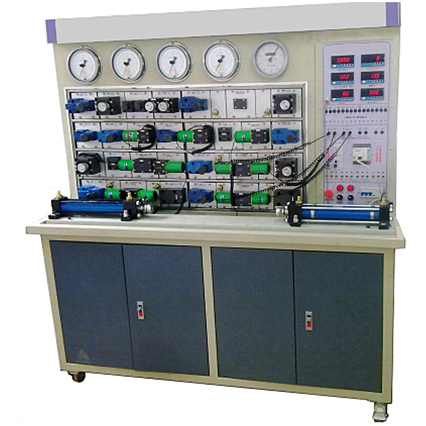
| 1 | Experimental bench | 1700×650×1800mm | 1 set | Chinese teachings |
| 2 | Practical tr*ning screen | U-shaped groove | 1 piece | Chinese teachings |
| Power pump station | ||||
| 3 | drive motor |
Rated power: 2.2 KW Rated voltage: 380V |
1 set | Kunshan, Jiangsu |
| 4 | Fixed vane pump | PV2R1-8F | 1 | kunshan river valley |
| 5 | tank | 90L | 1 | Chinese teachings |
| 6 | oil filter | MF-04 | 2 | T*wan Deng Sheng |
| 7 | Oil temperature and oil level gauge | YF-3” | 1 | T*wan Deng Sheng |
| Hydraulic Components | ||||
| 8 | Throttle valve stop valve |
Model: DV12-1-10/2 Diameter: 12mm Maximum working pressure: 35Mpa Flow range: 0-50L/Min |
2 | Beijing Huade Hydraulic |
| 9 | One-way valve |
Model: S10A Diameter: 10mm Maximum working pressure: 31.5Mpa Minimum opening pressure difference: 0.05MPa Q=30L/Min when flow rate = 6m/s |
2 | Beijing Huade Hydraulic |
| 10 | Relief valve (direct-acting type) |
Model: DBDH6P/100Mpa Diameter: 10mm Maximum back pressure: 31.5 Mpa Minimum opening pressure difference: 1.3MPa |
3 | Beijing Huade Hydraulic |
| 11 | Relief valve (pilot type) |
Model: DB10-1-30/100 Maximum back pressure: 31.5 Mpa Minimum opening pressure difference: 0.5Mpa Control maximum pressure: 31.5Mpa Minimum opening pressure difference: 0.5MPa |
1 | Beijing Huade Hydraulic |
| 12 | Control Valve |
Model: 2FRM5-30/15Q Rated flow: 15L/Min Maximum working pressure: 21MPa Temperature and pressure effects: 2%-5% Flow adjustment range: 0-15L/min |
2 | Beijing Huade Hydraulic |
| 13 | Two-position four-way solenoid directional valve (single) |
Model: 4WE6C61/CG24 Diameter: 6mm Working pressure: 31.5Mpa 24V control single electromagnet |
2 | Beijing Huade Hydraulic |
| 14 | five trues | 2 | Chinese teachings | |
| 15 | force meter | YB-100 | 5 | H*tian Special Hydraulics |
| 16 | Copper tube | 8mm | Many roots | Chinese teachings |
| 17 | Pipe joint | multiple | Ningbo, Zhejiang | |
| 18 | Hydraulic component oil circuit transition plate | Aluminum alloy | Many | Chinese teachings |
| 19 | Flow Sensors |
Model: LWGY-6 Accuracy level: 0.5 Range: 0-10L/min |
1 | Shangh* |
| 20 | Flow display header | BT | 1 | suzhou |
| twenty one | Speed sensor | J3-D4C1 | 2 | Shangh* |
| twenty two | Speed display meter | BTAR | 1 | suzhou |
| twenty three | Power transmitter | PAS-P | 1 | suzhou |
| twenty four | Power display meter | DP3 | 1 | suzhou |
| Electrical components | ||||
| 25 | DC switching power supply (DC24V) | 8A | 1 | Chinese teachings |
| 26 | Three-phase circuit breaker | With leakage and short circuit protection | 1 | Chint Electrical Appliances |
| 27 | Electrical control unit | Relays, terminal blocks, etc. | 1 set | Chinese teachings |
| 28 | Electrical operation panel | Buttons, display instruments, etc. | 1 piece | Chinese teachings |
| Documentation | ||||
| 29 | Experimental Operation Manual | 1 volume | Chinese teachings | |
| Spare wearing parts | ||||
| 30 | Sealing tape (raw material tape) | 2 volumes | ||
| 31 | Sealing combination gasket | Φ22 | 8 | |
| 32 | power switch button | DS451 | several | |
| 33 | Electrical signal plugs and sockets | 4 sets | ||
| Tool list | ||||
| 34 | adjustable wrench | 6' | 1 handful | hardware tools |
| 35 | adjustable wrench | 12' | 1 handful | hardware tools |
| 36 | Dumb wrench | 10' | 2 handfuls | hardware tools |
| 37 | Allen wrench | 1.5~10mm | 1 set | hardware tools |
| 38 | "Ten" screwdriver | 6' | 1 handful | hardware tools |
| 39 | "One" screwdriver | 6' | 1 handful | hardware tools |
| 40 | "Ten" screwdriver | 3' | 1 handful | hardware tools |
| 41 | "One" screwdriver | 3' | 1 handful | hardware tools |
| 42 | Needle nose pliers | 1 handful | hardware tools | |
 Wechat scan code follow us

24-hour hotline+86 18916464525

Phone18916464525
ADD:Factory 414, District A, No. 6, Chongnan Road, Songjiang Science and Technology Park, Shanghai ICP: Sitemap