Shanghai Daiyu Education Equipment Manufacturing Co., Ltd.
Language:


| serial number | Practical tr*ning module name | M*n configuration | quantity | Remark | |
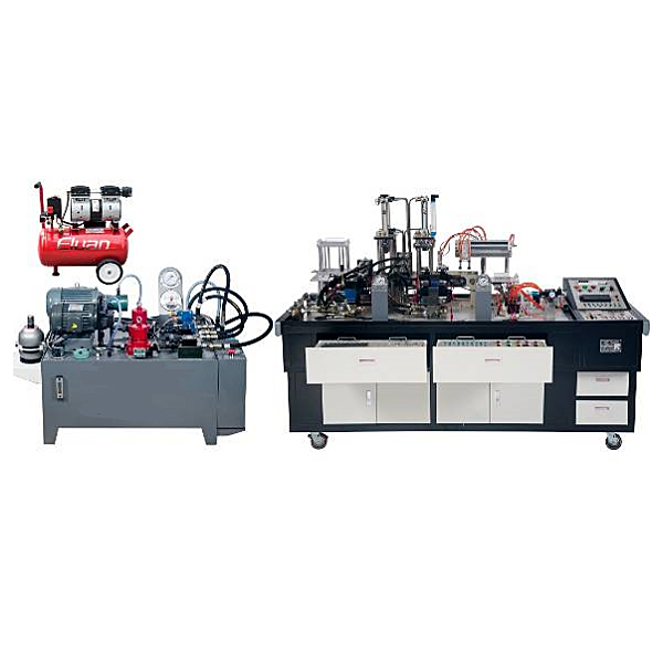
| 1 | Basic tr*ning module | Tr*ning platform | The platform adopts an iron double-layer matte dense spray-p*nted structure and is equipped with electrical control components, storage cabinets for tr*ning components, and tool drawers. There are 4 universal wheels installed at the bottom for easy movement and layout. Size: 2200mm×900mm×980mm | 1 set | |
| 2 | Air compressor | Nominal volume 24L, rated flow: 116L/min, rated output *r pressure 1MPa | 1 set | ||
| 3 | Supporting tools | Electrician tool set includes digital multimeter, wire strippers, needle nose pliers, diagonal pliers, screwdriver, tweezers, scissors, soldering iron, soldering iron stand, soldering wire, etc.; Allen wrench (nine-piece set), Allen wrench (4mm ) 1 set, 1 adjustable wrench (0-150mm), 1 adjustable wrench (0-250mm), 1 adjustable wrench (0-300mm), 2 double open end wrenches. | 1 set | ||
| 4 | Tr*ning accessories | 24 industrial hydraulic hoses (including quick connectors at both ends); 20 meters of *r pipe, 10 T-shaped tees (APE6), 10 pipe plugs (APE6); 1 pack of special tr*ning wires; instruction manual and tr*ning guide; Software CD (including PLC programming software and PLC program); fuses and other wearing parts. | 1 set | ||
| 5 | Hydraulic and pneumatic transmission simulation tr*ning software | This software uses graphics, text, animation, simulation and other interactive animation methods to demonstrate the comprehensive tr*ning system of hydraulic and pneumatic transmission, simulates the working process of the fully automatic steel rolling stamping line, and expl*ns the m*n teaching of the entire hydraulic and pneumatic course. The content includes basic definitions and principles of components to internal structure animations, and from theoretical hydraulic and pneumatic circuits to the application of actual hydraulic and pneumatic systems. This software combines the functions, structures, and functions of each component of currently commonly used hydraulic and pneumatic systems to comprehensively dissect the working principles and processes of hydraulic and pneumatic systems. | 1 set | ||
| 6 | Electrical control module | power control unit | The power control unit is composed of a total power supply control and protection unit, a power supply voltage indication unit, a system start/stop control unit, and a system power output unit. | 1 set | |
| 7 |
DW-01 control button module |
The button module is equipped with 5 illuminated reset button switches, 5 illuminated self-locking button switches, 1 emergency stop switch, 1 two-position rotary switch, 1 three-position rotary switch, 1 buzzer, and all contacts of the above devices. All points are led to the panel to facilitate the connection of the control loop. | 1 set | ||
| 8 |
DW-02B Mitsubishi host module |
Using Mitsubishi's third generation 3U series host, FX3U-32MR 16-point input/16-point relay output, plus analog combination modules 4AD, 2DA, 4 inputs, 2 outputs. | 1 set | ||
| 9 |
DW-03 relay control module |
It is equipped with 8 DC 24V relays and 1 DC 24V time relay. All contacts are led to the panel to facilitate the connection of the control circuit. All switch value (including coil) terminals are led to the panel, and there are corresponding indicator lights when the coil is powered. | 1 set | ||
| 10 | DW-04 proportional speed valve control module | Power supply voltage: DC 24V±10%; power: 50W; control voltage: ±9V±2%; load resistance: 10Ω; maximum output current: 2200mA; oscillation frequency: 2.5kHz, etc. | 1 set | ||
| 11 | Measurement and control instruments | Shock resistant pressure gauge | YN-60ZQ/10MPa measuring range 0-10MPa, built-in methyl silicone oil | 2 | |
| 12 | turbine flow sensor | LGWY-6 | 1 | ||
| 13 | Smart measuring instrument | The smart instrument adopts LED digital display, and the internal control adopts advanced artificial intelligence adjustment (AI) algorithm and has self-tuning (AT) function. | 1 | ||
| 14 | Hydraulic component module | Double acting hydraulic cylinder | Stroke 200mm | 2 | |
| 15 | Two-position three-way solenoid directional valve | 3WE6A61B/CG24N9Z5L | 2 | ||
| 16 | Two-position four-way solenoid directional valve | 4WE6C61B/CG24N9Z5L | 1 | ||
| 17 | One-way valve | RVP8 | 1 | ||
| 18 | Hydraulic control check valve | SV10PA2 | 2 | ||
| 19 | One-way throttle valve | DRVP8-1-10B/ | 2 | ||
| 20 | Two-way flow valve (speed regulating valve) | 2FRM5-31B/15QB | 2 | ||
| twenty one | Direct acting relief valve | DBDH6P10B/100 | 1 | ||
| twenty two | Direct acting sequence valve | DZ6DP1-5X/75 | 1 | ||
| twenty three | Direct acting pressure reducing valve | DR6DP1-5X/75YM | 1 | ||
| twenty four | pressure relay | HED4OP15B/100Z14L24 | 2 | ||
| 25 | Proportional speed regulating valve | 2FRE6B-20B/10QR | 1 | ||
| 26 | branch valve | 2 tees and 2 crosses, 45# steel surface nickel plated | 1 set | ||
| 27 | Plate valve base | The surface of 45# steel is nickel-plated, and the back of the valve adopts a spring buckle design. The oil inlet and outlet on the front of the valve plate are equipped with anti-leakage quick connectors, which are led out from the front. | 1 set | ||
| 28 | Stacking valve tr*ning module | Stacked relief valve | MBP-01-C-30 | 1 | |
| 29 | Stacked relief valve | MBB-01-C-30 | 1 | ||
| 30 | Stacked pressure reducing valve | MRP-01-B-30 | 1 | ||
| 31 | Stacked sequence valve | MHP-01-C-30 | 1 | ||
| 32 | Superposition pressure switch | MJCS-02-A-2-DC24 | 1 | ||
| 33 | Superposition pressure switch | MJCS-02-B-2-DC24 | 1 | ||
| 34 | Superimposed one-way throttle valve | MSA-01-X-10 | 1 | ||
| 35 | Superimposed one-way throttle valve | MSB-01-Y-10 | 1 | ||
| 36 | Stacked hydraulic control check valve | MPW-01-2-40 | 1 | ||
| 37 | Three-position four-way solenoid directional valve | DSG-01-3C2-D24-N1-50 (O type) | 1 | ||
| 38 | Three-position four-way solenoid directional valve | DSG-01-3C4-D24-N1-50 (Y type) | 1 | ||
| 39 | Three-position four-way solenoid directional valve | DSG-01-3C9-D24-N1-50 (P type) | 1 | ||
| 40 | Solenoid directional valve with emergency handle | DSG-01-3C3-DC24V-CA-N1 (H type) or HD-4WEM6H-7X/CG24N9 Z5L | 1 | ||
| 41 | Stacked valve double group basic valve plate | 45# steel surface nickel plating treatment | 1 | ||
| 42 |
Stacked electromagnetic one-way throttle valve |
FMS-G0-02A(24V) | 1 | ||
| 43 | Stacked valve three sets of basic valve plates | 45# steel surface nickel plating treatment | 1 | ||
| 44 | Stacked valve top plate | 45# steel surface nickel plating treatment | 2 | ||
| 45 | Stacked valve pressure gauge connection plate | 45# steel surface nickel plating treatment | 2 | ||
| 46 | Pneumatic component module | Double acting cylinder |
MAL-CA-32×125-S-LB (including magnetic switch and strap) |
2 | |
| 47 | Pneumatic triplex | AC2000-08 | 1 | ||
| 48 | Pressure regulating valve (with pressure gauge) | SR200-08 | 2 | ||
| 49 | Single solenoid controlled two-position three-way valve | 3V210-08NC/DC24V | 1 | ||
| 50 | 3V210-08NO/DC24V | 1 | |||
| 51 | Single solenoid controlled two-position five-way valve | 4V210-08/DC24V | 3 | ||
| 52 | Double electronically controlled two-position five-way valve | 4V220-08/DC24V | 2 | ||
| 53 | Three-position five-way solenoid directional valve | 4V230C-08/DC24V | 1 | ||
| 54 | Single *r-controlled two-position five-way valve | 4A210-08 | 2 | ||
| 55 | Single *r-controlled two-position three-way valve | 3A210-08NO | 2 | ||
| 56 | Single *r-controlled two-position three-way valve | 3A210-08NC | 2 | ||
| 57 | Dual *r-controlled two-position five-way valve | 4A220-08 | 2 | ||
| 58 | Air controlled delay valve | XQ230650 (normally closed type) | 1 | ||
| 59 | One-way throttle valve | ASC200-08 | 6 | ||
| 60 | Quick exhaust valve | Q-02 | 2 | ||
| 61 | shuttle valve | ST-01 | 2 | ||
| 62 | with valve | STH-01 | 2 | ||
| 63 | Roller lever mechanical valve | S3R-08 | 2 | ||
| 64 | Pneumatic valve base | 200M-3F | 2 | ||
| 65 | Pneumatic blind plate | 200M-B | 3 pieces | ||
| serial number | Practical tr*ning module name | M*n configuration | quantity | Remark |
| 1 | Industrial pump station fuel tank | Maximum volume 140L, 3mm steel plate, matte dense gr*n spray | 1 | |
| 2 | Fixed piston pump set | Fixed piston pump: 5MCY14-1B, displacement 5cc/r, system rated pressure: 10MPa; motor: three-phase AC voltage 380V, rated power: 3KW, rated speed 1420r/min, insulation B | 1 set | |
| 3 | Variable vane pump unit | Pressure-limiting variable vane pump: VP-08 rated flow 8L/min, system rated working pressure: 6.3MPa, motor: three-phase AC voltage 380V, rated power: 1.5KW, rated speed 1420r/min, insulation B | 1 set | |
| 4 | Dosing pump pressure regulating component | System pressure regulating valve base, pilot relief valve, two-position three-way electromagnetic reversing valve, direct-acting relief valve, one-way valve, etc. | 1 set | |
| 5 |
Variable vane pump pressure regulating assembly |
System pressure regulating valve base, direct-acting relief valve, one-way valve, etc. | 1 set | |
| 6 | Accumulator | NXQ1-L1.6/20-H (including bracket and hoop) | 1 | |
| 7 | *r cooler | AH0608 | 1 | |
| 8 | pressure line filter | QU-H10*20DLS | 2 | |
| 9 | Anti-wear hydraulic oil | L-HL32 | 100 liters | |
| 10 |
Shock-resistant st*nless steel pressure gauge |
YN-100ZQ/10MPa, measuring range 0-10MPa, accuracy level 2.5, built-in methyl silicone oil, including fixed bracket | 2 | |
| 11 | Pumping station electrical control box | The electrical control part of the pumping station includes intelligent thermometers, liquid level relays, AC contactors, thermal protectors, emergency stop buttons and other devices. All electrical component interfaces are open, with built-in terminal blocks, and automated remote control can be realized through PLC. | 1 | |
| 12 | Fuel tank accessories | 1 oil temperature and level gauge (YWZ-100T with temperature measurement function), 1 cleaning cover (FCL-04), 1 *r filter (QUQ2), 2 oil suction filters (WU-40×100J) | 1 set |
| serial number | Practical tr*ning module name | M*n configuration | quantity | Remark |
| 1 |
Simulation device control unit |
It adopts Mitsubishi's third generation 3U series host, FX3U-32MT 16-point input/16 transistor output, plus digital expansion module FX2N8EX, 8 inputs. | 1 set | |
| The loading tr*ning module consists of a well-type loading mechanism, an ejection cylinder, a pushing cylinder, and mechanical structural parts, which are m*nly made of hard aluminum and finished with sandblasting on the surface. | 1 set | |||
| 2 |
Pneumatic loading tr*ning module |
The transfer tr*ning unit adopts synchronous belt drive , ch*n drive and other transmission mechanisms, and is composed of cycloid hydraulic motor, roller sprocket, 12 rollers, synchronous pulley, base and other components. The mechanical structural parts are made of 45# steel finishing process, and the surface is nickel-plated. | 1 set | |
| 3 |
Transmission tr*ning module (hydraulic motor control) |
The steel rolling tr*ning module consists of steel rolling brackets, steel rolling rollers, roller sprockets, synchronous hydraulic cylinders, and linear displacement sensors (CWY-DW-150). The mechanical structural parts are made of 45# steel finishing technology, and the surface is nickel-plated. | 1 set | |
| 4 |
Double rolling steel tr*ning module (double cylinder synchronization) |
The stamping tr*ning module is made of stamping cylinder, top cylinder, positioning cylinder, and mechanical structural parts using 45# steel finishing technology, with nickel plating on the surface. | 1 set | |
| 5 | Stamping tr*ning module | The blanking tr*ning module consists of a vacuum suction cup, a rodless cylinder, a double cylinder, a stepper motor, and the mechanical structural parts are finished with hard aluminum and surface sandblasted. | 1 set | |
| 6 |
Blanking tr*ning module (pneumatic manipulator) |
 Wechat scan code follow us

24-hour hotline+86 18916464525

Phone18916464525
ADD:Factory 414, District A, No. 6, Chongnan Road, Songjiang Science and Technology Park, Shanghai ICP: Sitemap