Shanghai Daiyu Education Equipment Manufacturing Co., Ltd.
Language:


| serial number | name | Specification | quantity | unit | Remark | |
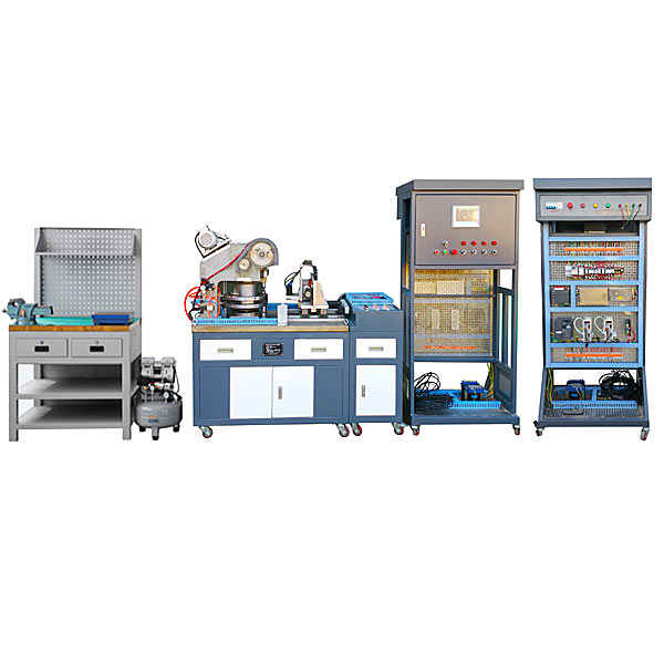
| 1 | Tr*ning platform | Iron double-layer matt dense spray-p*nted structure, 40mm thick casting flat table top, storage cabinet under the table, 2 drawers above the cabinet, size: 1100mm×700mm×1500mm | 1 | tower | ||
| 2 | console | Iron double-layer matte dense texture spray-p*nted structure, there is a storage cabinet under the table, and a drawer above the cabinet, size: 400mm×700mm×900mm | 1 | tower | ||
| 3 | Electrical control cabinet | Power control module | It consists of three-phase power m*n switch (with leakage and short-circuit protection), three-phase fuse, AC contactor, thermal relay, intermediate relay, switching power supply, key switch, emergency stop button, stop-start button (red, green), system control Composed of knob switch and indicator light | 1 | set | |
| 4 | programmable controller module | Siemens S7-200 SMART CPUST40 | 1 | set | Choose 1 from the second option | |
| 5 | Mitsubishi FX3U-48MTES/A | 1 | set | |||
| 6 | touch screen module | Siemens 7 inches, TFT true color, 65k colors | 1 | set | ||
| 7 | Motor drive module | Rotary switch, stepper motor driver M542, servo motor driver TSTE 15C, isolation transformer (380V/220V), Mitsubishi FR-E740-0.75k-CHT inverter | 1 | set | ||
| 8 |
Machinery equipment parts |
transmission mechanism | It m*nly includes typical transmission mechanisms such as belt drive (synchronous belt, triangle belt), ch*n drive (single row ch*n), gear drive (spur gear), etc. | 1 | set | |
| 9 | Two-dimensional feeding components (cross slide) | It m*nly consists of ball screw nut p*r (lengths are 528mm and 485mm respectively; nominal diameter 20mm; lead 5mm; right-hand rotation), linear guide r*ls and slide blocks (lengths 455mm and 335mm; width 15mm), work surface, bearings ( Angular contact bearings, deep groove ball bearings), bearing seats, end covers, pads, etc. | 1 | set | ||
| 10 | Turret parts | It is m*nly composed of upper and lower octagonal disc positioning pins, upper and lower octagonal disc positioning pin brackets, lower octagonal disc blanking holes, sprockets, ch*ns, upper and lower octagonal discs, transmission shafts, tapered roller bearings, supports, end covers, etc. | 1 | set | ||
| 11 | Mold | It adopts real CNC molds, including 4 types of molds: square hole mold, round hole mold, w*st hole mold, and triangle mold, and also includes 1 set of mold calibration sticks. | 1 | set | ||
| 12 | Mechanical punching mechanism | It is m*nly composed of punch bed, gear, end cover, crankshaft, bearing bush, bracket, motor base, bearing, unloading pulley device, etc. | 1 | set | ||
| 13 | Upper and lower octagonal disc pneumatic positioning modules | M*nly composed of single electronically controlled two-position five-way valve, pressure regulating filter, shaft cylinder, tee, PU *r pipe, quick-change joint, *r pump, etc. | 1 | set | ||
| 14 | clutch mechanism | It is m*nly composed of brackets, bearings, bushings, dial pins, electromagnetic clutches, electromagnetic brakes, etc. | 1 | set | ||
| 15 | tool | electrician tool kit | Including digital multimeter, wire strippers, needle nose pliers, diagonal pliers, screwdriver, tweezers, scissors, soldering iron, soldering iron stand, soldering wire, etc. | 1 | set | |
| 16 | Copper rod | One end is φ18, one end is φ14, and one end is φ30. | 2 | root | ||
| 17 | Rama | 1 | pieces | |||
| 18 | Slotted screwdriver | 10" through core slotted screwdriver | 1 | Bundle | ||
| 19 | Internal and external circlip pliers | 1 p*r each of str*ght nose and curved nose 9-inch inner and outer circlip pliers | 4 | Bundle | ||
| 20 | Rubber hammer, hammer | 1 round hammer (1.5 pounds) and 1 rubber hammer | 1 | set | ||
| twenty one | Wrench assembly | 9-piece set of hexagonal wrenches; 1 set of 150mm and 250mm adjustable wrenches; 1 set of 14-17 open end wrenches; 1 set of 7 and 17-end torx combination wrenches; 1 set of M14, M18, and M27 round nut wrenches | 1 | set | ||
| twenty two | ch*n cutter | 420~530 | 1 | Bundle | ||
| twenty three | handwheel | Outer diameter 100 | 1 | set | ||
| twenty four | movable handle | The thread is M8 | 1 | set | ||
| 25 | Measuring tools | scribed tablet | 300mm×300mm | 1 | piece | |
| 26 | Vernier caliper | Measuring range: 0~300mm, graduation value: 0.02mm | 1 | Bundle | ||
| 27 | Depth Vernier Caliper | Measuring range: 0~200mm, graduation value: 0.02mm | 1 | Bundle | ||
| 28 | square ruler | 200×130×12.5mm | 3 | Bundle | ||
| 29 | lever dial indicator | 0~0.8mm, graduation value: 0.01mm; including adapter and magnetic base | 1 | indivual | ||
| 30 | Dial indicator | 0~10mm; including adapter and magnetic watch base | 1 | indivual | ||
| 31 | micrometer | 0~25mm, 25~50mm, 50~75mm, 1 each | 3 | Bundle | ||
| 32 | Steel ruler | 500mm | 1 | Bundle | ||
| 33 | feeler gauge | Measuring range: 0.02~1.00mm | 1 | Bundle | ||
| 34 | Accessories | Parts box, programming cable, product supporting CD (software, user manual, program, etc.) | 1 | set | ||
| 35 |
Mechanical assembly and benchwork assembly virtual simulation software |
Using 3D virtual simulation technology and AVI video playback method, the interface is vivid and beautiful, easy to learn and use, which can increase students' interest in learning and deepen students' understanding and application of knowledge. Through the three-dimensional disassembly and assembly video animation, the disassembly and assembly process of the gearbox, clutch worm transmission mechanism, gear reducer, intermittent rotary table, punch mechanism, power source, feeding mechanism and other modules are vividly displayed. The following functions can be realized: basic knowledge and introduction of fitter assembly technology, structure and working principle of the m*n components of fitter assembly technology , virtual disassembly and assembly of gearbox, three-dimensional animation video explanation and demonstration, virtual disassembly and assembly of clutch worm transmission mechanism, three-dimensional animation video explanation and demonstration Virtual disassembly and assembly of gear reducer, 3D animation video explanation and demonstration. Virtual disassembly and assembly of intermittent rotary table , 3D animation video explanation and demonstration. Virtual disassembly and assembly of punch mechanism, 3D animation video explanation and demonstration. Virtual disassembly and assembly of power source, 3D animation video explanation. Demonstration: Virtual disassembly and assembly of the feeding mechanism, 3D animation video explanation demonstration |
1 | set | ||
| 36 | Computer Desk | Used to place the computer, with four universal wheels with brakes installed underneath, size: 560mm×600mm×1020mm | 1 | tower | ||
| 37 | computer | M*nstream brands | 1 | tower | Prepared by user | |
 Wechat scan code follow us

24-hour hotline+86 18916464525

Phone18916464525
ADD:Factory 414, District A, No. 6, Chongnan Road, Songjiang Science and Technology Park, Shanghai ICP: Sitemap