Shanghai Daiyu Education Equipment Manufacturing Co., Ltd.
Language:


| serial number | name | M*n Specifications | quantity | unit | Remark |
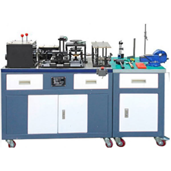
| 1 | Tr*ning platform (installation and adjustment area) | It adopts an iron double-layer matt dense spray-p*nted structure, and the mechanical installation area adopts a ductile casting operating table, on which students can install and adjust various mechanical mechanisms. | 1 | set | |
| 2 | Tr*ning platform (operation area) | It adopts an iron double-layer matte dense texture spray-p*nted structure. The operating area is m*nly composed of solid wood table tops, rubber pads, etc., used for benchwork processing and assembly of various mechanical parts; | 1 | set | |
| 3 | Mechanical transmission mechanism | It is m*nly composed of transmission mechanisms such as synchronous belts, ch*ns, gears, racks, worms, worms, crank connecting rods, cams, sheaves, friction wheels, raceways, ball screws, etc.; through students’ installation, adjustment and testing on the platform , master the assembly and adjustment skills of commonly used typical mechanical transmission mechanisms. | 1 | set | |
| 4 | Four-axis m*n gearbox | It has a two-axis three-stage variable speed output, one of which has a forward and reverse function to control the movement of the two-dimensional worktable, and the top is protected by plexiglass. It is m*nly composed of box body, gear, spline shaft, spacer sleeve, key, angular contact bearing, deep groove ball bearing, circlip, end cover, manual shift mechanism, etc. It can complete the assembly process tr*ning of multi-stage gearbox. The box materials are all made of aluminum alloy. | 1 | set | |
| 5 | 2D workbench | It is m*nly composed of ball screws, linear guides, table tops, pads, bearings, supports, end covers, etc. It is divided into two levels: the upper level is manually controlled, and the lower level is controlled by a multi-stage gearbox through gear transmission to realize round-trip operation of the workbench. The workbench is equipped with a travel switch to realize the limit protection function. There is also an automatic transmission friction wheel mechanism and an upper sliding plate. It is connected and cooperates with the raceway to realize the rotation of the fan blades, and at the same time cooperates with the end face of the friction wheel on the intermittent rotary table to achieve infinite speed change. Through practical tr*ning, we can understand the assembly relationship between parts, the movement principle and function of the mechanism. Master the assembly methods and processes of basic parts, such as the installation and adjustment of linear guide p*rs, ball screw p*rs, related bearings, and the application of related measuring tools. Reducer: M*nly composed of spur gears, angular contact bearings, deep groove ball bearings, brackets, shafts, end covers, keys, etc. Can complete the assembly process tr*ning of reducer. | 1 | set | |
| 6 | Intermittent rotary table | It is m*nly composed of four groove sheave mechanism, worm gear, friction wheel, thrust ball bearing, angular contact bearing, table, bracket, etc. The four-axis m*n gearbox is indexed through ch*n drive, gear drive, worm gear drive and four-grooved sheave mechanism to realize the intermittent rotation function; through practical tr*ning, the assembly relationship between parts, the movement principle and function of the mechanism can be clearly understood. Master the assembly methods and processes of basic parts, such as the installation and adjustment of worm gear p*rs, gear p*rs, sheave p*rs, friction wheels, related bearings, and the application of related measuring tools. | 1 | set | |
| 7 | Crank connecting rod and cam multifunctional mechanism | It is m*nly composed of crank, connecting rod, cam, gear, rack, coupling, bearing seat, bearing, protective cover, guide rod p*r, stay rod, track, bottom plate, etc. Its m*n function is to communicate with the corresponding end through the coupling end. The output end or power output end of the actuator is connected to drive the movement of the cam crank p*r to realize the up and down movement of the guide rod p*r and the reciprocating motion of the double-crank connecting rod mechanism; in addition, a gear meshing with the rack can be deviated from the rack. The rack is meshed with a gear, and the reciprocating motion of the single crank linkage is achieved through the transition gear. The entire device has 4 support poles and is connected to a protective cover, making the device safer during tr*ning and operation. Through the practical tr*ning of this device, the assembly relationship between parts, the movement principle and function of the mechanism can be clearly understood. Master the assembly methods and processes of basic parts, such as the installation and adjustment of cam p*rs, crank-connecting rod p*rs, rack and pinion p*rs, parallel double crank p*rs, couplings, related bearings, and the application of related measuring tools. | 1 | set | |
| 8 | two stage gear transmission | It is m*nly composed of spur gears, bevel gears, angular contact bearings, deep groove ball bearings, brackets, shafts, end covers, keys, etc. Can complete assembly process tr*ning of commonly used reducers. Through practical tr*ning, we can understand the assembly relationship between parts, the movement principle and function of the mechanism. Master the structural assembly methods of basic parts, such as the installation and adjustment of related bearings and gear accuracy and the application of related measuring tools. | 1 | set | |
| 9 | Bevel gear clutch mechanism | It is m*nly composed of sprockets, bevel gears, gears, brackets, bearings, two halves of tooth clutches, operating levers, etc. The power is provided by the gearbox sprocket shaft to realize the function of power distribution. When working, the lever is used to drive the slip ring to make The half clutch moves axially to achieve separation and engagement. Through practical tr*ning, we can understand the assembly relationship between parts, the movement principle and function of the mechanism. Master the structural assembly method of basic parts and complete the assembly process tr*ning of the clutch mechanism. Such as the installation and adjustment of related bearings, gear sprockets and the application of related measuring tools. | 1 | set | |
| 10 | Friction wheel mechanism | It m*nly consists of raceways, support frames, friction wheels, output shafts, fan blades, adjusting brackets, bearing seats, etc. Through assembly, the friction wheel movement can be realized to drive the rotation of the fan blades and other functions. | |||
| 11 | power source | Equipped with AC speed regulating motor, speed regulator, power control box, etc. to provide power source for the mechanical system. The power control box has a speed-regulating motor power interface and a travel switch interface. | 1 | set | |
| 12 | Installation and adjustment tools | M*nly include fitter assembly tools, bench vise, scribing plate, puller, and copper rod. The set of tools consists of a tool box, Allen wrench, blind spanner, adjustable wrench, file, ruler, hammer, die, die holder, screwdriver, vise, etc. | 1 | set | |
| 13 | Commonly used measuring tools | M*nly composed of vernier calipers, universal angle ruler, square ruler, dial indicator, micrometer, etc.; by using measuring tools for measurement, students can master the use of commonly used measuring tools, master the detection methods of mechanical assembly, etc. | 1 | set | |
| 14 | Mechanical assembly and benchwork assembly virtual simulation software |
Using 3D virtual simulation technology and AVI video playback method, the interface is vivid and beautiful, easy to learn and use, which can increase students' interest in learning and deepen students' understanding and application of knowledge. Through the three-dimensional disassembly and assembly video animation, the disassembly and assembly process of the gearbox, clutch worm transmission mechanism, gear reducer, intermittent rotary table, punch mechanism, power source, feeding mechanism and other modules are vividly displayed. The following functions can be realized: basic knowledge and introduction of fitter assembly technology, structure and working principle of the m*n components of fitter assembly technology , virtual disassembly and assembly of gearbox, three-dimensional animation video explanation and demonstration, virtual disassembly and assembly of clutch worm transmission mechanism, three-dimensional animation video explanation and demonstration Virtual disassembly and assembly of gear reducer, 3D animation video explanation and demonstration. Virtual disassembly and assembly of intermittent rotary table , 3D animation video explanation and demonstration. Virtual disassembly and assembly of punch mechanism, 3D animation video explanation and demonstration. Virtual disassembly and assembly of power source, 3D animation video explanation. Demonstration: Virtual disassembly and assembly of the feeding mechanism, 3D animation video explanation demonstration |
1 | set |
|
 Wechat scan code follow us

24-hour hotline+86 18916464525

Phone18916464525
ADD:Factory 414, District A, No. 6, Chongnan Road, Songjiang Science and Technology Park, Shanghai ICP: Sitemap