DY-S3 transparent stamping simulation training platform
Release time:2024-05-15 20:30viewed:times
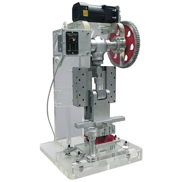
1. Overview:
This machine is a miniaturized and improved production machine. It has a small size, can be moved at will, and is suitable for classroom teaching . This product can complete punching, stretching, forming and other actions. It has the advantages of simple structure, easy operation, low price, no noise and pollution, and can use 220V voltage, so it can be used in any electric place. It fills
the gap of no experimental machine in mold teaching. This machine can conduct classroom simulation demonstrations of transparent disassembly and assembly molds , and can see the movement process of the mold during experiments, providing designers with more practical thinking about various mechanisms in mold design.
2. M*n features:
1. The fuselage and supporting molds are all made of imported plexiglass. This plexiglass material has good corrosion resistance and wear resistance, and does not discolor for a long time, and the demonstration effect is realistic.
2. This set of products is designed with six sets of matching molds for users to choose.
3. Technical parameters:
1. AC power supply: single-phase 220VAC 50HZ
2. Supporting mold size: 200×150mm
3. Demonstration table size (mm): 450×450×820
4. Overall machine weight: about 70kg
4. Supporting injection mold (Optional)
1 punching die 200×150mm
2 blanking die 200×150mm
3 bending die 200×150mm
4 drawing die 200×150mm 5
progressive die 200×150mm
6 compound die 200×150mm 5. Single chip
microcomputer , plc Programmable design and control virtual simulation software This software is developed based on unity3d. It has built-in task books and experimental prompts. It adopts the form of three-dimensional roaming. It can control movement through the keyboard, the mouse to control the direction of the lens, and the mouse wheel to control the distance of the picture. It can rotate 360 degrees, three-dimensional There are electrical diagrams p*nted on the walls . 1. Equipment component assembly: Follow the highlighted prompts to find the component control rack. You can drag components from the component library according to the electrical component layout diagram and place them on the component control rack. The component library is equipped with control panels, switching power supplies, micro relays, and PLCs. , frequency converter, stepper motor , AC motor, servo motor, servo driver, stepper driver, interface board, operation panel, circuit breaker, servo motor interface, digital display voltmeter, there will be a prompt when the selection is wrong. 2. Technical indicator measurement: Select a multimeter to check the servo motor connection cable and the servo driver with BOP panel. Adjust the left and right buttons to the ohm range, drag the black and red test leads and insert them into the R, S, T, U, V, W, and ground phases respectively for testing. For resistance value, according to the highlighted prompt, find the power switch in the scene, drag the pen or multimeter to measure whether the power is on. 3) Connection of electrical components: According to the electrical wiring diagram, connect the power lines and control lines, highlight the interface, connect the driver, interface board, power line, servo motor, encoder, PLC, and relay in order, and turn on the m*n power After switching on the switch, servo power switch, and faulty circuit switch, a fault code will be prompted and you can select the cause of the fault from three items. 4) Parameter adjustment test: Turn on the power to adjust the speed, set the driver parameters according to the requirements of the mission statement, perform inching control/analog speed adjustment/multi-stage speed control, and observe the three-dimensional servo motor motion control. Select any of the 6 PLC programs and then adjust the servo drive analog speed. The PLC parameters are adjustable. Set the drive parameters and enter the three-dimensional servo motor motion control interface and electrical display interface. The operation panel is equipped with servo start, low speed, medium Speed, high speed, servo stop, torque limit, abnormal reset, forward/reverse rotation selection, 0-10 sliding control (the electrical panel displays the value in real time). 5) Inspect the three-dimensional virtual simulation machine of the servo system mask machine, observe its structure, inject fault points, select multiple fault causes, and locate faults. Connect the fault causes with the corresponding detection and positioning methods, and troubleshoot after selecting the correct ones. Connect the cause of the f*lure with the corresponding solution. 6) Control process plan, optional single machine mode and online mode of inching control/analog speed regulation/multi-stage speed regulation control, call up the control panel, display the operation of 3 production lines, perform real-time control, optional inching, low and medium High-speed, start and stop control, the speed is adjustable. According to the control plan, the system automatically determines the performance of the production line and submits a disclosure record.


 Wechat scan code follow us
