Shanghai Daiyu Education Equipment Manufacturing Co., Ltd.
Language:

PRODUCT

PRODUCT CENTER

DYGC-07 "Typical Parts" measured drawing training experimental device

Release time:2024-05-15 01:00viewed:times
  • DYGC-07 "Typical Parts" measured drawing training experimental device
1. Product Features    
1. Actualization of projects: taking typical actual parts as the tr*ning object;
2. Systematization of functions: three-in-one tr*ning mode of looking for parts by looking at pictures, parts surveying and parts drawing, and parts drawing; one view, two
views, three views and multi-views The tr*ning process of parts from simple to complex.
3. Popularization of students: small, combined, portable tr*ning devices, in groups of two or three, allowing as many students as possible to get
sufficient tr*ning opportunities;
4. Standardization of teaching: supporting tr*ning instructions, both teaching and learning are very convenient and convenient. The effect is remarkable;
5. Management facilitation: parts, measurement tools and instructions are all placed in a refined box, making management very convenient.
2. Product parameters  

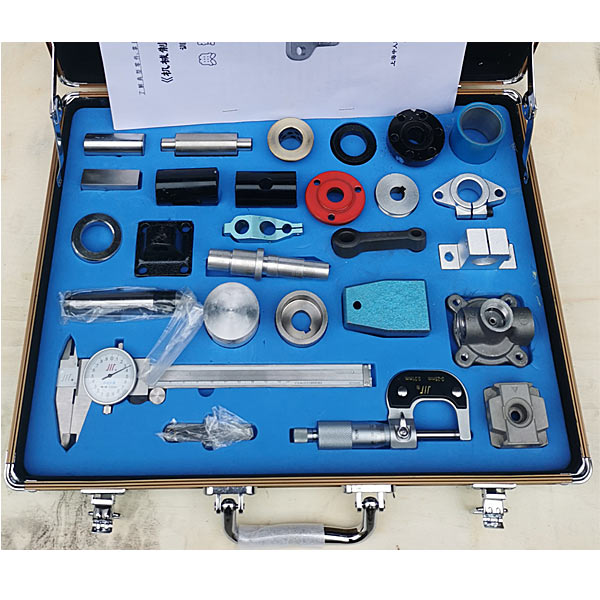
"Typical Parts" actual measurement drawing tr*ning combination device
project Parameters project Parameters
Dimensions 40×30×7cm weight 5(kg)
Typical parts
(24 pieces/set)
One-view parts: optical shaft, copper sleeve, gasket, etc.
Two-view parts: cuboid, keyway shaft, pulley, flange plate, coupling, bracket, etc.
Three-view parts: base, low-speed shaft, bearing seat, etc.
Multi-view parts : Piston, valve body, etc.
Measuring tools Vernier caliper, outer diameter millimeter, arc template, etc. type Portable combined type (testing parts, measurement tools and
instructions are all placed in a refined color box)
Teaching materials Practical tr*ning instructions and tr*ning reports (including electronic drafts);
3. Product functions  
tr*ning mode Tr*ning content
1. Tr*ning on looking at pictures to find parts;    
2. Tr*ning on parts surveying and mapping;
3. Tr*ning on projection drawing of parts;
4. Tr*ning on three-dimensional drawing.
Tr*ning 1: One-view parts surveying and mapping tr*ning  
Tr*ning 2: Two-view parts surveying and mapping tr*ning
Tr*ning 3: Three-view parts surveying and mapping tr*ning  
Tr*ning 4: Multi-view parts surveying and mapping tr*ning
4. Comprehensive integrated tr*ning virtual simulation system for vocational skills: The model
in the software can be rotated 360°, enlarged, reduced, and translated, and is equipped with universal interactive buttons: return, home page, and help. There are prompts during all virtual simulation tasks, and the software automatically checks the box after completing a task. There are experimental tasks 1 and basic three-dimensional above the tool library. (When the model is rotated, the XYZ space coordinate icon automatically follows the rotation.) A. Plane and three-dimensional: The experimental steps are divided into experimental tasks (text prompt tasks) - building models (drag and drop in the tool library The model is put into the three-projection plane system, and the projection is automatically displayed. There will be a prompt when the selection is wrong) - Change the posture (change by clicking the up, down, left and right arrows) - Select the projection (enter the answer interface, select the three-dimensional projection map completed at this time among the 6 items) ) B. Cutting three-dimensional: The experimental steps are divided into experimental tasks (text prompt tasks) - building the model (drag the model in the tool library into the three-projection plane system, and automatically display the projection) - marking the projection situation (as a three-dimensional projection icon Determine, select the corresponding label symbol in the 14 blank columns) C. Intersecting three-dimensional: The experimental steps are divided into experimental tasks (text prompt tasks) - digging holes (select any digging model, at this time, you will be able to dig holes in the XYZ space coordinates Select any surface, the model will be switched at the same time, and a coordinate slider will appear. According to the displacement of the slider, the model will appear with a corresponding section plane) - aperture change (select 1-4 apertures) - rear through hole - select projection (enter the answer interface) , select the three-dimensional projection image completed at this time among the 8 items) 2. Assembly A, assembly assembly: The experimental steps are divided into experimental tasks (text prompt tasks)-select the assembly model (8 models are optional)-assembly assembly Body (select the tool library model according to the selected model and drag and drop to combine) - Sectioning the combined body (you can select any surface in the XYZ space coordinates, the model is switched at the same time, and a coordinate slider appears. According to the displacement of the slider, the model appears Corresponding section plane)—Select the side projection (enter the answer interface and select the correct side projection among the 3 items based on the known front and horizontal projections) B. Combination picture reading: The experimental steps are divided into experimental tasks (text Prompt task)—Select the combination section view (8 types of pictures are av*lable)—Build the combination model (select the tool library model according to the selected model and drag and drop the combination)—Section the combination (you can select any surface in the XYZ space coordinates, The model is switched at the same time, and a coordinate slider appears. According to the displacement of the slider, the model appears with a corresponding section plane) - Select the left view (enter the answer interface, select the correct left view among the 3 items based on the known m*n view and top view) View) 3. Assembly A, mechanical transmission mechanism : 8 types of mechanisms (worm gear, rack and pinion, screw transmission, out-of-plane meshing gear, in-plane meshing gear, space spur bevel gear, belt drive , ch*n drive) optional , after selecting, the model will appear in the toolbar. Drag and drop the model freely to combine it. After the combination is completed, the model can be operated. Each mechanism comes with an introduction, video demonstration, and drawing method. There are 6 questions in the answering interface, and each question has 4 options. B. Gear oil pump: Select the tool library model according to the prompts to gradually build the model. You can choose the introduction, drawing method, and animation principle (the internal movement principle of the model is visible) to learn. There are 2 questions in the answering interface, each with 4 options. C. Mechanical mechanism construction: 2 types of mechanisms (2-DOF robotic arm, 3-DOF robotic arm). Select the tool library model according to the prompts to gradually build the model. After the combination is completed, the model can be operated. Each mechanism comes with an introduction and video demonstration. . There are 2 questions in the question-answering interface (which can only be entered after both models have been built), each with 4 options.

DAIYUWechat scan code follow us

  • 24-hour hotline+86 18916464525

  • Phone18916464525

 ADD:Factory 414, District A, No. 6, Chongnan Road, Songjiang Science and Technology Park, Shanghai ICP: Sitemap