Shanghai Daiyu Education Equipment Manufacturing Co., Ltd.
Language:


| name | Technical parameters and specifications |
|
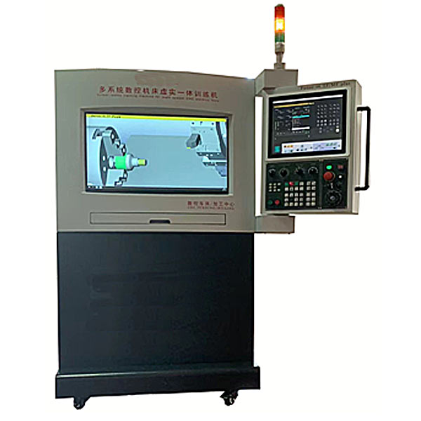
CNC system |
CNC system: simulates FANUC Oi-TF PLUS and FANUC Oi-MF PLUS; 1. Position display [POS]: machine tool coordinates, absolute coordinates, relative coordinates; 2. Program function [PROG]: display program functions, inspection, and current section , sub-single block, program editing [EDIT], [ALTER] [INSERT] [DELETE], automatic mode, background editing, program lock, program transfer function [F input], [F output]; 3. Tool correction [OFS/ SET]: workpiece movement, coordinate system, shape correction, wear correction W, MACRO variable setting, metric and inch unit setting; 4. System parameters [SYSTEM], transmission parameters, machine tool parameters, editing parameters; 5. Address and numeric keys, input , Reset [RESET], [CAN] function keys; 6. Abnormal alarm display, the alarm code is the same as the real machine operation error display. Example 1: X-axis over travel displays "alarm" 500 OVER TRAVEL: +X, the alarm is cancelled . mode, you need to move the The time and error code of the first alarm; equipped with network RJ45 interface data transmission function, which can transmit the program through the network; |
|
Operation panel and functions |
Mode selector button function 1. [EDIT] program editing mode: edit and modify program content; 2. [DNC] online processing mode: program is processed while transmitting; 3. [AUTO] automatic processing mode: program is processed automatically; 4. [MDI] ] Command input mode: used for parameter setting and temporary program input; 5. [MPG] Handwheel mode: Use the handwheel to adjust; 6. [JOG] Manual feed mode: Use the axial keys to feed manually; 7. [ RAPID] Rapid movement mode: Use the axial keys to move quickly; 8. [ZRN] Reference point return mode: Each axis returns to the machine tool reference point; 9. Rapid movement adjustment knob, feed speed adjustment knob, spindle speed adjustment knob; 10. Single block ignore [BDT], single step execution [SBK], selective stop [M01], cycle start [CYCLE START], cycle pause [FEED HOLD]; 11. Spindle forward rotation, spindle stop, spindle reverse rotation, coolant , work light, protective door; 12. Program protection lock, emergency stop button, tool change button; 13. Push-button axial buttons X+, X-, Y+, Y-, Z+, Z-; 14. Alarm indicator light, Axial reference point indicator light; 15. Industrial handwheel, handwheel speed knob, handwheel axial knob, etc.; |
|
CNC machine tool simulation- lathe part |
1. 3D solid structure, horizontal lathe, automatic chuck, 12-station turret; 2. Machine tool base, spindle chuck, clamping jaws, turret, tool, t*lstock, center; 3. Rapid movement: X-axis 20 m/min, Z axis: 24m/min; 4. Maximum cutting speed: X axis 6m/min, Z axis: 8m/min; 5. According to the industrial operation control panel, dynamic interactive simulation runs the entire CNC machine tool; 6. Collision Detection function: When the spindle is not rotating, the contact between the tool and the material is considered a collision. 7. Simulation speed adjustment: 0% ~ 200%; 8. Sound effect switch, system volume adjustment; 9. Workpiece material setting: maximum diameter = 250mm, maximum length = 450mm; 10. Lathe tool setting: diamond knife (80 degrees , 55 degrees, 35 degrees), triangular cutter (60 degrees), thread cutter, groove cutter, circular cutter, drill bit, peach-shaped cutter, round nose cutter, center drill, wire tapping, end face cutter. 11. Tool magazine installation: tool loading, unloading, modification, deletion; 12. Standard viewing angles: top view (XY), front view (ZX), side view (YZ), stereoscopic (ISO) 13. Commonly used zoom viewing angles: material range, The scope of the bed and the scope of the machine; 14. Free operating perspective: translation, rotation, zooming in, and zooming out; 15. The simulation design includes cutting fluid splashing and chips flying out when cutting to the workpiece; 16. Sound (tool movement sound, cutting sound effects, Spindle rotation sound, alarm sound); 17. Workpiece size linear measurement function: diameter, thickness, length; 18. Factory value restoration function; 19. CNC program local computer hard disk and U disk input and output functions; 20. CNC program external computer RS232 input and output functions; 21. DNC online processing function; |
 Wechat scan code follow us

24-hour hotline+86 18916464525

Phone18916464525
ADD:Factory 414, District A, No. 6, Chongnan Road, Songjiang Science and Technology Park, Shanghai ICP: Sitemap