Dysk-5A multi-axis CNC processing center virtual reality training training device
Release time:2024-05-13 20:30viewed:times
1. Product Introduction
Intelligent manufacturing is the m*n direction of building a strong manufacturing country, and CNC machine tools are an important part of intelligent manufacturing. In response to the national call, our company introduced the world's advanced CNC software technology and developed this series of CNC machine tool virtual and real integrated tr*ning machines. The tr*ning machine is a combination of software and hardware, with advanced functions, reliable quality, and diversified optional CNC systems.
Currently, such products include: FANUC series FANUC 0i-TF Plus (turning version), FANUC 0i-MF Plus (three-axis milling version); Mitsubishi series Mitsubishi M80 (three-axis milling version); Siemens series SINUMERIK 828D (turning version) ), (three-axis milling version), SINUMERIK 840D (five-axis milling version); HEIDENHAIN series (five-axis milling version).
2. Product Features
The five-axis five-linkage CNC machining center is a high-end CNC machine tool with complex processing procedures on the market. Programmers and operators also require very professional personnel to be competent. It is a high-precision CNC machine tool. Practical problems such as high machine tool cost, difficulty in m*ntenance, and high rep*r costs prevent schools from purchasing in large quantities, resulting in students being unable to tr*n normally.
At present, professional teachers can only expl*n in the classroom through textbooks. Students do not have the knowledge and experience of real machine tools during the learning process. If they directly take students to tr*n on real machine tools, students will experience great psychological pressure and may easily become nervous and cause broken tools, Practical factors include machine collision, high loss of materials and tools, easily damaged machine tools, unsafe conditions, and high teaching costs.
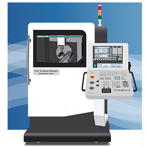
In order to solve the above factors, our company has developed the latest generation of one-machine multi-purpose five-axis CNC machining center virtual and real integrated tr*ning machine. This equipment combines software and hardware and has the functions of programming, processing and debugging systems, and can realize AC and BC axes. The simulation operation of the interchangeable five-axis CNC machining center can be manually programmed or input CAD/CAM program for simulated processing. The highly simulated software CNC system interface is the same as the real CNC system, equipped with real operating panels and handwheels, so that students can experience the same operating experience of real CNC machine tools during the learning process, laying a solid foundation for the next step of operating real machine tools. Special design. The m*n hardware of the equipment consists of four parts.
1. The cabinet of the five-axis CNC machining center's integrated virtual and real tr*ning machine adopts a vertical structure to meet the real CNC machine tool operating experience. The cabinet is formed by bending and welding of high-strength steel plates. The surface is sprayed with iron matte dense texture, and the bottom is equipped with 4 universal pulleys and equipped with brake devices for easy movement and fixation.
2. The simulated machine tool uses a 32-inch LCD monitor to more realistically display in 3D the exact same mechanical structure as the real machine tool. It has a representative five-axis five-linkage machining center (milling) with AC axes and BC axes. , this simulated machine tool can enlarge, reduce, rotate, translate and other multi-view images, and the spindle rotation, tool cutting, tool changing, iron filings, coolant, etc. are accompanied by sound effects during operation, allowing students to have an experience of operating a real machine tool;
3. CNC The system is displayed on a 17-inch touch screen. For operations such as editing programs, modifying parameters, and setting tools, you can directly tap the corresponding function keys on the screen with your fingers, giving you the same operating experience as a real CNC system;
4. CNC machine tool operation panel, The handwheel adopts standard industrial type, allowing students to have the experience of operating a real machine tool while learning.
3. M*n technical parameters of the product (Siemens series)
3.1: CNC system
1. CNC controller: simulates SINUMERIK 840D-5 axis (professional version);
2. Operation function panel: functions are fully simulated and designed according to the function keys of the actual SINUMERIK 840Dsl controller ;
(1) [Machine] processing operation: display machine coordinates, absolute coordinates and processing status;
(a) (AUTO) coverage, process control , block search, setting functions;
(b) (MDA) load MDA, save MDA, Process control, setting function
(c) (JOG) TSM, setting work offset, positioning, end milling, oscillation function, setting function, metric and inch view switching;
measuring workpiece: calibration probe, edge, distance between 2 edges, circular convex Table;
measuring tools: manual length, manual radius, calibration fixed point;
(2) [PROGRAM] program editing:
(a) Function keys (editing): select tool, search, select, copy, paste, cut, renumber, Setting, closing;
(b) Cycle command editing (drilling): center hole drilling, drilling, reaming, deep hole drilling, boring, tapping, thread milling, position, repeat position;
(c) Cycle command editing (Milling): Surface milling: cavity (rectangular cavity, circular cavity), boss (rectangular boss, circular boss, polygonal boss), groove (longitudinal groove, arc groove, open groove, long hole) , thread milling;
(d) Cycle command editing (contour milling): new contour, contour call, path contour, drilling center hole, pre-drilling, cavity, cavity rem*ning material, boss, boss rem*ning material;
(e ) Cycle command editing (others): blank, setting, rotation plane (cycle800), milling cutter positioning, high-speed setting, conversion, subroutine;
(f) Linear arc: tool, str*ght line, circle center, arc radius, spiral , polar coordinates, processing functions;
3. [OFFSET] Tool correction:
(a) Tool geometry correction (Geometry): basic tool data setting, measuring tool, cutting edge, unloading, tool magazine selection, classification;
(b) Tool wear Correction (Wear): classification;
(c) Coordinate system correction G54-G57: work offset setting, valid, overview, datum, det*led information;
(d) Work area restrictions;
4. [PROGRAM MANNGER] program management: execution, new, Open, select, copy, paste, cut, search, attribute, delete;
5. [ALARM] abnormal alarm: alarm list, alarm record;
6. Program zero position icon: dynamically displayed according to the tool correction value;
7. Overall operating environment: save and import function, completely save the status of the operation settings, and can import and restore the current status, convenient for viewing the setting data as a reference for evaluation and correction;
8. Workpiece material: save and load Function (file format: STL);
9. Tool settings: add, modify, delete, import and export of tool data;
10. Tool magazine installation: import and export, commonly used tool magazine;
11. Simulation speed: 10 %, 50%, 100%, 160%, 250%, 500%, 900%, 990%, MAX; The simulation speed can be limited
to 500% to help students check the program and perform actions;
12. Workpiece settings: Workpiece Color, pad height, vise size;
13. Workpiece size measurement: angle measurement (absolute angle, two-sided angle), arc measurement (three-point circle);
14. Machine production status: supports real-time monitoring and management of machine production status System;
15: Spindle speed and feed speed detection function:
(1) The spindle rotates correctly and the spindle speed is within the specified range.
(2) The feed speed is within the specified range.
16: Tool and material collision detection function:
(1) If the spindle is not rotated or the rotation direction is wrong, and the tool comes into contact with the material, it is considered a collision.
(2) If the non-cutting edge part of the tool comes into contact with the material, it is considered a collision.
(3) The cutting feed speed is too fast and exceeds the allowable range, which is regarded as a collision.
17: Collision detection function: tool and material, vise, turntable, collision detection;
spindle and material, vise, turntable, collision detection;
3.2: Operation panel and functions
1. Mode selector button function
(1) AUTO automatic Execution mode - automatic program execution;
(2) MDA command input mode - used for parameter setting and temporary program input;
(3) JOG cutting feed mode - cutting feed using axial keys;
(4) RAPID rapid movement mode - Use the axial keys to move quickly;
2. Feed speed adjustment knob
(1) Start [CYCLESTSRT], pause [CYCLESTOP], single block [SINGLE BLOCK], reset [RESET];
(2) Spindle forward, spindle stop, Spindle reversal;
(3) Program protection lock, emergency stop, tool magazine rotation button, coolant, safety door open/close;
(4) Push-button axial buttons: [X], [Y], [Z], [4TH AXIS], [5TH AXIS], positive [+], negative [-], [RAPID], release button, axial return [REF.POINT];
(5) Handwheel button [MPG], handwheel speed knob, Handwheel axial knob;
3.3: Machining center simulation function (3 types)
3.3.1: Vertical five-axis five-linkage milling machining center (A/C axis)
1. 3D solid construction, vertical five-axis five-linkage milling machining center ( X, Y, Z, A, C axes);
2. Including machine bed base, sheet metal casing, automatic door, spindle head, vise, Z-axis tool adjuster, cutter, automatic tool changer ATC, casing display /Hide function;
3. The simulation design includes cutting fluid splash, flying chips when cutting the workpiece, sounds (tool movement sound, cutting sound effects, spindle rotation sound, alarm sound);
4. Collision detection function: spindle or tool and Material, vise, turntable, collision detection;
5. Simulation speed adjustment: 10%, 50%, 100%, 160%, 250%, 500%, 900%, 990%, MAX; the simulation speed can be limited to 500 Within %, help students check the program and perform actions;
6. Workpiece size measurement function: length, width, height, str*ght line, angle, arc;
7. Quickly restore factory value function;
8. CNC program import and export function;
9. Stroke: X-axis 650mm, Y-axis 650mm, Z-axis 550mm;
10. Rapid movement: X/Y/Z axis 18m/min, A/C axis 24rpm;
11. Maximum cutting feed speed: X/Y/Z axis 6m /min, A/C axis 24rpm;
12. Workbench: cradle-type rotary table (A-axis + C-axis)
13. Based on the real machine tool operation control panel, dynamic interactive operation simulates the entire CNC machine;
14. Workpiece settings:
(1) Maximum size of rectangular parallelepiped workpiece: length × width × height = 230 × 200 × 200mm;
(2) Size of cylindrical workpiece: diameter × length × elongation = 120 × 250 × 200mm;
(3) Workpiece position: adjustable in the center ;
15. Milling tool settings: face milling cutter, end milling cutter, round nose cutter, ball cutter, chamfering cutter, edge finder, positioning drill, thread tapping, drill bit, milling cutter, rough boring cutter, fine boring cutter
16. Tool magazine installation: tool installation, modification, deletion; 17.
Standard viewing angle: top view (XY), front view (ZX), side view (YZ), stereoscopic (ISO);
18. Commonly used zoom perspectives: material range, bed range, machinery range;
19. Free operation perspective: translation, rotation, zoom;
20. Calibration operation functions: Z-axis setting, photoelectric length corrector, X/Y-axis setting, photoelectric edge finder function;
3.3.2: Vertical Five-axis five-linkage milling machining center (B/C axis)
1. 3D solid construction, vertical five-axis five-linkage milling machining center (X, Y, Z, B, C axes);
2. Including machine bed, sheet Gold shell, automatic door, spindle head, vise, Z-axis tool adjuster, tool, automatic tool changer ATC, case display/hide function;
3. The simulation design includes cutting fluid splashing and flying out when cutting to the workpiece Chips, sounds (tool movement sounds, cutting sound effects, spindle rotation sounds, alarm sounds);
4. Collision detection function: spindle or tool and material, vise, turntable, collision detection;
5. Simulation speed adjustment: 10%, 50%, 100%, 160%, 250%, 500%, 900%, 990%, MAX; the simulation speed can be limited to 500% to help students check the program and perform actions;
6. Workpiece size measurement function: length, Width, height, str*ght line, angle, arc;
7. Quickly restore factory value function;
8. CNC program import and export function;
9. Stroke: X-axis 670mm, Y-axis 550mm, Z-axis 550mm;
10. Rapid movement: X /Y/Z axis 18m/min, B/C axis 24rpm;
11. Maximum cutting feed speed: X/Y/Z axis 6m/min, B/C axis 24rpm;
12. Workbench: cradle-type rotating table (B axis + C axis)
13. Based on the real machine tool operation control panel, dynamic interactive operation simulates the entire CNC machine;
14. Workpiece settings:
(1) Maximum size of rectangular parallelepiped workpiece: length × width × height = 230 × 200 × 200mm;
(2) Cylindrical workpiece size: diameter × length × elongation = 120 × 250 × 200mm;
(3) Workpiece position: adjustable in the center;
15. Milling tool settings: face milling cutter, end milling cutter, round nose cutter, Ball cutter, chamfering cutter, edge finder, positioning drill, screw tap, drill bit, milling cutter, rough boring cutter, fine boring cutter, quick drill;
16. Tool magazine installation: Tool installation, modification, deletion;
17. Standard viewing angles: upward view (XY), front view (ZX), side view (YZ), stereoscopic view (ISO);
18. Commonly used zoom viewing angles: material range, bed range, mechanical range;
19. Free operation perspective: Translation, rotation, scaling;
20. Calibration operation functions: Z-axis setting, photoelectric length corrector, X/Y-axis setting, photoelectric edge finder function;
3.3.3: Vertical three-axis three-linkage milling Machining center
1. 3D solid structure, vertical milling machining center (X, Y, Z axes);
2. Including machine bed base, sheet metal shell, automatic door, spindle head, vise, Z-axis tool corrector, and cutting tools , automatic tool changer ATC, casing display/hide function;
3. Simulation design includes cutting fluid splash, flying chips when cutting to the workpiece, sounds (tool movement sound, cutting sound effects, spindle rotation sound, alarm sound);
4 , Collision detection function: spindle or tool and material, vise, turntable, collision detection;
5. Simulation speed adjustment: 10%, 50%, 100%, 160%, 250%, 500%, 900%, 990% , MAX; can limit the simulation speed to 500% to help students check programs and perform actions;
6. Workpiece size measurement function: length, width, height, str*ght line, angle, arc;
7. Quickly restore factory value function;
8 , CNC program import and export function;
9. Stroke: X-axis 830mm, Y-axis 510mm, Z-axis 590mm;
10. Rapid movement: X-axis 18m/min, Y-axis 18m/min, Z-axis 18m/min;
11. Cutting Maximum feed speed: X-axis 6m/min, Y-axis 6m/min, Z-axis 6m/min;
12. Based on the real machine tool operation control panel, dynamic interactive operation simulates the entire CNC machine;
13. Workpiece settings:
(1 ) Maximum size of rectangular workpiece: length × width × height = 500 × 310 × 300mm;
(2) Workpiece position: adjustable in the center;
14. Milling tool settings: face milling cutter, end milling cutter, round nose cutter, ball cutter , chamfering cutter, edge finder, positioning drill, screw tap, drill bit, milling cutter, rough boring cutter, fine boring cutter, quick drill;
15. Tool magazine installation: tool installation, modification, deletion;
16. Standard Viewing angles: top view (XY), front view (ZX), side view (YZ), stereoscopic view (ISO);
17. Commonly used zoom viewing angles: material range, bed range, machine range;
18. Free operation perspective: translation, rotation , zoom;
19. Calibration operation functions: Z-axis setting, photoelectric length corrector, X/Y-axis setting, photoelectric edge finder function;
3.4: Machining center - program instructions
1. Program execution cutting simulation (X, Y, Z, A/B, C axis) five-axis five-linkage professional version (supports tool tip following function);
(1) Motion instructions: G00, G01, G02, G03;
(2) Pause time instructions: G04;
(3) Plane selection instructions: G17, G18, G19;
(4) Tool radius compensation instructions: G40, G41, G42, G43;
(5) Workpiece size, inch/metric: G70, G71;
(6) Workpiece size, absolute/incremental size command: G90; G91;
(7) Approaching reference point: G74, approaching fixed point: G75;
(8 ) ) Feed rate commands: G94, G95, G96, G97;
(9) Workpiece coordinate system: SUPA G53 G54, G55, G56, G57;
(10) Support drilling and tapping cycles: CYCLE81-CYCLE89;
(11) Support G01 Automatic chamfering of C angle (CHF), automatic chamfering of R angle (RND);
(12) Support SWIVEL CYCLE800;
(13) Support G01 A angle (ANG) command function;
(14) Support G291 ISO command format;
(15) Support TRAORI (RTCP) tool tip center following function;
(16) Supports instructions HOLE1, HOLE2, CYCLE801, CYCLE802;
(17) Supports slot instructions SLOT1, SLOT1, POCKET3, POCKET4, LONGHOLE;
(18) Supports MACRO macro program function:
Program variables: Local variables;
arithmetic instructions: add +, subtract -, multiply x, divide /, SIN, COS, TAN, SQRT square value, ABS absolute value;
conditional judgment: EQ equals, NE not equal, GT greater than, LT less than, GE greater Equal to, LE less than or equal to;
divergence control: unconditional divergence GOTO n; conditional divergence IF [conditional expression] GOTO n; repeated execution of WHILE [conditional expression];
2. M code auxiliary function:
(M00) program stop, (M01) selectivity Stop, (M02) End of program, (M03) Spindle forward, (M04) Spindle reverse,
(M05) Spindle stop, (M06) Machining center tool change, (M08) Coolant on, (M09) Coolant off, (M98) Call subprogram, (M99) End of subprogram, (M30) End of program and return to the beginning of the program;


 Wechat scan code follow us
