Shanghai Daiyu Education Equipment Manufacturing Co., Ltd.
Language:


| serial number | name | Specification | quantity | Remark |
| 1 | feeler gauge | 150mm0.02-1 | 1 | |
| 2 | multipurpose level | 1 | Can measure horizontal, vertical, 45° | |
| 3 | combination square | 0-102mm | 1 | |
| 4 | Dial indicator | 0.01mm/grid | 1 | |
| 5 | Magnetic watch base | 203X63X6(LengthXWidthXHeight) | 1 | |
| 6 | digital tachometer |
Measuring range 0-999.9RPM/1000-9999.9RPM |
1 | |
| 7 | Oil bottle | 200ml | 1 | |
| 8 | Steel ruler | 0-1000mm | 1 | |
| 9 | Vernier caliper | 0-150mm | 1 | |
| 10 | Outside diameter micrometer | 0-25mm | 1 | |
| 11 | Steel ruler | 0-300mm | 1 | |
| 12 | Allen wrench | 1.5#-10# | 1 set (9 pieces) | |
| 13 | Dumb wrench | 10-12 | 2 | |
| 12-14 | 2 | |||
| 14-17 | 2 | |||
| 14 | Noise meter | SJ-1 | 1 | |
| 15 | Phillips screwdriver | 6 inches | 2 | |
| 16 | Slotted screwdriver | 3 inches 4 inches | 1 each | |
| 17 | Needle nose pliers | 1 | ||
| 18 | adjustable wrench | 8 inches | 1 | |
| 19 | half round file | Radius is about R8.5 | 1 | Can file 17mm large inner hole |
| 20 | round file | 7 inch | 1 | |
| twenty one | vise | 6 inches | 1 | |
| twenty two | With tension measuring instrument | 1 | ||
| twenty three | rubber hammer | 2 | ||
| twenty four | flat file | 10 inches | 2 | |
| 25 | Hacksaw | 1 | ||
| 26 | Flat nose pliers | 5 inch | 1 set |
| serial number | Name and specification | quantity |
| 1 | Gear 1m2Z36 | 3 |
| 2 | Gear 2m2Z24 | 2 |
| 3 | Gear 3m2Z48 | 2 |
| 4 | Gear 4m1.5Z26 | 2 |
| 5 | Gear 5m1.5Z60 | 2 |
| 6 | Gear 6m1.5Z64 | 1 |
| 7 | Gear 7m1.5Z80 | 1 |
| 8 | Gear 8m2Z80 | 2 |
| 9 | Gear 9m2Z90 | 2 |
| 10 |
Small sprocket P=12.7Z=15 |
1 |
| 11 |
Middle sprocket P=12.7Z=20 |
1 |
| 12 |
Large sprocket P=12.7Z=30 |
1 |
| 13 | Small pulley 34° | 1 |
| 14 | Middle pulley 34° | 1 |
| 15 | Large pulley 34° | 1 |
| 16 |
The pinion m2Z36 is an incorrect design |
1 |
| 17 |
The large gear m2Z48 is wrongly designed. |
1 |
| 18 |
The small pulley is 37°. This is a wrong design. |
1 |
| 19 |
Large pulley 31° This is a wrong design |
1 |
| 20 |
Small sprocket This is an incorrect design P=12.7Z=15 |
1 |
| twenty one |
Large sprocket This is an incorrect design P=12.7Z=30 |
1 |
| twenty two |
Small helical gear I15° Mn=1.5z=26 |
1 |
| twenty three |
Large helical gearⅠ15° Mn=1.5Z=69 |
1 |
| twenty four |
Small bevel gear m=2Z=25 |
1 |
| 25 |
Large bevel gear m=2Z=50 |
1 |
| 26 |
Small helical gear II22° Mn=1.5Z=26 |
1 |
| 27 |
Large helical gear II22° Mn=1.5Z=69 |
1 |
| 28 | Rolling bearing seat UP203 | 8 |
| 29 | Rolling bearing seat UP205 | 4 |
| 30 | Sliding bearing seat HZ020 | 4 |
| 31 | Drive shaft 1 | 9 |
| 32 | Drive shaft 2 | 2 |
| 33 | Drive shaft 3 | 2 |
| 34 | sleeve coupling | 1 |
| 35 | Claw elastic coupling | 2 sets |
| 36 | Flexible intermediate disk | 2 |
| 37 |
Cover cushion 82.8 high (24 pieces) 76.5 high (4 pieces) 33 high (4 pieces) 82.5 high (4 pieces) |
36 |
| 38 | washer | 4 |
| 39 |
Adjustment shims (3 types) 0.1mm-12 pieces; 0.2, 0.3, mm-12 pieces each; |
48 |
| 40 | Axis Panel 1 | 1 |
| 41 | Axis Panel 2 | 1 |
| 42 | Belt drive plate | 1 |
| 43 | sprocket panel | 1 |
| 44 | gear panel | 1 |
| 45 | Expansion board 1 | 1 |
| 48 | Expansion board 2 | 1 |
| 49 | Expansion board 3 | 1 |
| 50 | Shaft end ret*ning ring 1 | 10 |
| 51 | Shaft end ret*ning ring 2 | 12 |
| 52 | Shaft end ret*ning ring 3 | 10 |
| 53 | Connecting rod Ⅰ | 1 |
| 54 | Connecting rod 2 | 1 |
| 55 | crank | 1 |
| 56 | Slider pin | 1 |
| 57 | joystick | 1 |
| 56 | crank pin | 1 |
| 57 | articulated shaft | 1 |
| 58 | Sensor connection shaft | 1 |
| 59 | mechanism slider | 2 sets |
| 60 | Mechanism bracket | 2 sets |
| 61 | Mechanism slide r*l | 1 |
| 62 | Linear displacement bracket | 1 |
| 63 | Photoelectric encoder bracket | 1 |
| 64 | linear displacement connecting shaft | 1 |
| 65 | horseshoe card | 1 |
| 66 | Photoelectric encoder | 1 |
| 67 | linear displacement sensor | 1 |
| 68 | brake hub | 1 set |
| 69 | Motor activity adjustment nut | 4 |
| 70 | brake | 1 set |
| 71 | Motor adjustment seat | 1 |
| 72 |
Motor coupling inner hole¢12 |
2 |
| 73 | AC motor 6IK250RA-CF | 1 set |
| 74 | AC reduction motor 5IK60RGN-CF | 1 set |
| 75 | Optical axis motor base | 1 |
| 76 | Motor and other high base | 1 |
| 77 | ch*n tensioner | 1 |
| 78 | Contour point adjustment block | 2 |
| 79 | With tension measuring instrument | 1 |
| 80 | ch*n | 1 |
| 81 | Belt type A 900 | 1 |
| 82 |
Wheel groove gauge 1 Y type |
1 |
| 83 |
Wheel groove gauge 2 Z, A, B, C type |
1 |
| 84 |
Wheel groove gauge 3 D, I type |
1 |
| 85 |
Belt type gauge 1 Y, Z, A, B, C type |
1 |
| 86 |
Rack gauge: m=1.5, 2; m=2.5, 3; m=4, 5; |
1 each, 3 in total |
| 87 | Backing plate 180×70×10 | 1 |
| 88 | clip | 67 |
| 77 | Round head flat key 5×5×20 | 15 |
| 78 | External hexagonal screw M4×10 | 8 |
| 79 | External hexagonal screw M8×110 | 50 sets (pieces) |
| 80 | External hexagonal screw M8×25 | 20 sets (pieces) |
| 81 | External hexagonal screw M8×60 | 6 sets (pieces) |
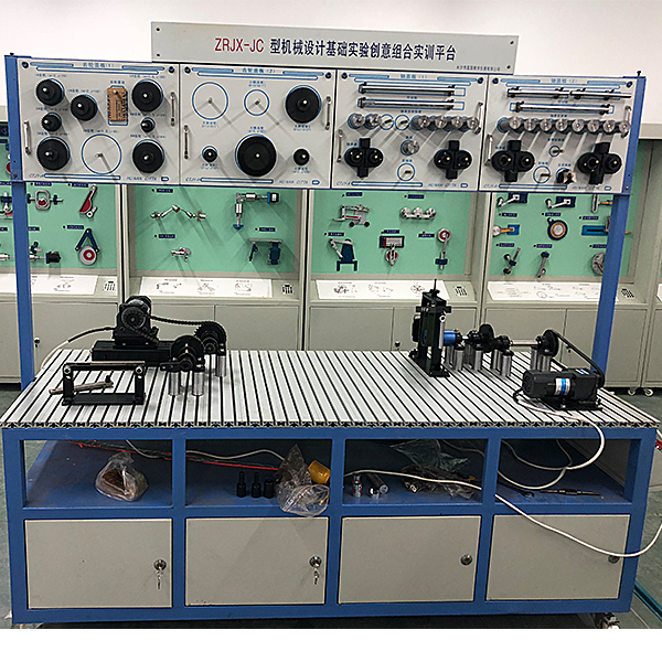
| 82 | Mechanical system innovative design overlap assembly tr*ning test bench | 1 |
| 83 | Electrical control box | 1 set |
| 84 | Data collection box | 1 |
| 85 | Institutional testing software | 1 set |
 Wechat scan code follow us

24-hour hotline+86 18916464525

Phone18916464525
ADD:Factory 414, District A, No. 6, Chongnan Road, Songjiang Science and Technology Park, Shanghai ICP: Sitemap