Shanghai Daiyu Education Equipment Manufacturing Co., Ltd.
Language:


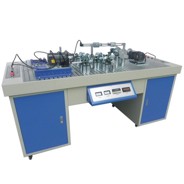


The m*n function of this experimental bench is to provide students with a practical tr*ning platform for manually assembling complex mechanical systems, allowing students to design and assemble complex mechanical systems that can achieve different motion requirements. At the same time, the experimental platform has designed the locations for installing sensors on the m*n components , and is equipped with a detection system and data processing software. Students can understand the movement rules and kinematic characteristics of moving components in different complex mechanical systems through the movement parameter change curves.
2. Experimental functional requirements:
1. It uses a single mechanical part to achieve various transmission effects in mechanical transmission through physical operations, allowing students to apply the theories they have learned in practice.
2. Understand the impact of part processing accuracy on assembly in actual installation, and understand the concepts and functions of various geometric tolerances such as parallelism, str*ghtness, coaxiality, orientation, positioning, and runout .
3. Master the use of various work card measuring tools at work.
4. Through the installation of mechanical transmission, fully understand the various damages, vibration and noise caused by installation errors on the working process of mechanical transmission.
5. It is required to design and install the sensor position on the m*n components, and equip it with a detection system and data processing software. Through experiments, we can understand the displacement, speed, and acceleration of the direct-action mechanism; the swing angular displacement, angular velocity, angular acceleration, and rotational axis speed of the swing mechanism. Method for measuring motion parameters such as rotational unevenness. Through the motion parameter change curve, we can understand the motion rules and kinematic characteristics of the moving components in different complex mechanical systems.
6. By testing and analyzing various transmission mechanisms installed, the impact of installation errors on test accuracy can be summarized, and the effects of theory and actual measurement can be compared in a timely manner to analyze and identify existing problems.
3. Experimental bench structural composition requirements:
(1) The experimental bench is divided into two experimental operation work areas, left and right, which are driven by two motors respectively . Two groups of students can perform experimental operations on the experimental bench at the same time. The experimental operation work area on the left can m*nly complete the mechanical transmission innovative overlap and transmission characteristic test experiments; while the experimental operation work area on the right can m*nly complete the mechanism motion innovative overlap and mechanism motion characteristic test experiments.
(2) The installation platform is made of standard T-slot aluminum alloy profiles. The distance between the movable supports can be adjusted arbitrarily. The overlap is flexible and can be assembled with belt (V belt, flat belt, synchronous belt) transmission, ch*n (section) Pitch ch*n, large pitch ch*n) transmission, various gears (spur gears, helical gears, spiral teeth, bevel gears) transmission, single universal coupling transmission, double universal coupling transmission, sheave mechanism transmission, and more A variety of motion mechanisms such as planar connecting rods and cams can be used to assemble various types of complex mechanical systems. There are more than 20 typical assembly solutions. Students can design their own components and assemble innovative works, giving full play to their initiative and innovative spirit.
(3) Parameters such as transmission ratio, number of teeth and center distance, etc. All transmission gear tr*ns must be supported by polished rods and fixed with set screws, making adjustments easy and fast, and overlapping easy and fast.
(4) It is required that the length of all rod components and the eccentricity of the slider can be adjusted steplessly, and the impact of changes in this parameter on the motion characteristics of the mechanism is analyzed.
(5) The drive speed-regulating motor is required to have stepless speed regulation to meet the different motion requirements of the experimental mechanism.
(6) The detection system needs to integrate data collection and motor adjustment control. Equipped with multiple photoelectric rotary encoders, linear displacement sensors, and powerful computer processing software. On the experimental bench, the transmission and motion patterns of various transmission mechanisms such as single-axis, multi-axis combination multi-stage gear transmission , ch*n transmission, belt transmission , and universal joint transmission, crank rockers, crank sliders, cams and other combination mechanisms can be analyzed , for data collection and motion analysis. The m*n contents of the test are: the motion displacement, speed, and acceleration of the direct-action mechanism; the swing mechanism, swing angular displacement, angular velocity, and angular acceleration; the rotation speed and speed fluctuation motion rules of the transmission shaft, and the test and analysis of the rotation unevenness of the rotation motion of the mechanism, etc.;
(7) The system supporting software is required to be rich in content, including communication method selection, mechanical transmission characteristic testing, mechanism motion characteristic testing and analysis, experimental result analysis and curve fitting, 20 typical assembly mechanism virtual assembly and motion simulation, and experimental bench introduction. Contents such as experimental operation guidance are comprehensive and open.
(8) The system is equipped with various commonly used mechanical installation and measurement tools. Through installation by themselves, students can master the role of measurement tools in practical work and improve their understanding of working condition measuring tools.
(9) A "PCI communication" interface is set at one end of the experimental bench to realize the experimental operation of communication between the computer and the experimental bench.
(10) 32 single-ended or 16 differential analog inputs, or combined input mode; 12-bit A/D conversion resolution; A/D converter sampling rate up to 100KS/s; 4096 sampling FIFO buffer on the card ; 2,500VDC isolation protection; programmable g*n of each input channel; supports software, internal timer trigger or external trigger sampling mode
(11) Mechanical tr*ning safety education virtual simulation software (demo and copyright certificate provided): This software is developed based on unity3d and can be deployed on the cloud server or used in the local environment. The software adopts the form of three-dimensional roaming and can be controlled through the keyboard Move, the mouse controls the direction of the camera. There are mechanical safety distance experiments, mechanical safety protection device experiments, and basic mechanical safety protection design assessments. When the experiment is in progress, the three-dimensional roaming screen uses arrows and footprints to prompt you to move to the experimental location, and circles around the mechanical objects are displayed. The working radius has been determined, and the experimental process is accompanied by a dialog box reminder of the three-dimensional robot.
A. The content of the mechanical safety distance experiment includes the safety distance experiment to prevent upper and lower limbs from touching the danger zone (divided into two fence heights and opening sizes). After selecting to enter, GB23821-2009 "Mechanical Safety to Prevent Upper and Lower Limbs from Touching the Danger Zone" pops up in front of the camera. "Safe Distance" requirements, error demonstration: The experimental process is that after the human body enters the working radius of the mechanical object and is injured, the red screen and voice prompts that the human body has received mechanical damage, and returns to the original position and conducts the next experiment. The last step is the correct approach.
B. Mechanical safety protection device experiments are divided into safety interlock switches, safety light curt*ns, safety mats, safety laser scanners and other protection device experiments. Optional categories (safety input, safety control, safety output, others), manufacturers, products List (safety interlock switch, safety light curt*n, safety mat, safety laser scanner, safety controller, safety relay, safety guardr*l). There is a blue flashing frame reminder at the installation location. Experimental process: select the safety guardr*l and install it, select the safety interlock switch (or select the safety light curt*n, safety mat, safety laser scanner) and install it, select the safety controller and install it in the electrical control box , select the safety relay and install it in the electrical control box, click the start button on the electrical control box. If you enter a dangerous area, the system will sound an alarm and the mechanical object will stop working. Select the reset button on the electrical control box to stop.
C. The basic assessment of mechanical safety protection design requires the completion of the installation of the mechanical safety system, and the correct installation of safety guardr*ls, safety interlock switches, safety light curt*ns, safety mats, safety laser scanners, safety controllers, safety relays, 24V power supplies, signal lights and Emergency stop button, the assessment is divided into ten assessment points. Some assessment points have 3 options, which are freely chosen by the students. After selecting the final 10 assessment points, submit for confirmation, and the system will automatically obt*n the total score and the score of each assessment point. .
D. The software must be on the same platform as a whole and cannot be displayed as separate resources.
(12) Teacher teaching design system (providing demonstration and copyright certificate): This software is developed based on unity3d, with optional 6-level image quality. It is equipped with the design and virtual disassembly and assembly of reducers and shafting structures, and the design and simulation of common mechanical mechanisms. Mechanism resource library, typical mechanical mechanism (virtual disassembly and assembly of gasoline engine), the software is a whole software and cannot be individual resources.
A. Reducer design and virtual disassembly interface can choose worm gear bevel gear reducer, two-stage expanded cylindrical gear reducer, bevel cylindrical gear reducer, coaxial cylindrical gear reducer, bevel gear reducer, and one-stage cylindrical gear reducer. Gear reducer.
Worm and bevel gear reducer: After entering the software, the assembly content is automatically played, and each step in the video has text explanations.
Two-stage expandable cylindrical gear reducer: After entering the software, the content is played in the form of a video. The video content should include: part name (scan the QR code to see the name of the part), disassembly and assembly demonstration (including disassembly and assembly), virtual disassembly Installation (including overall, low-speed shaft, medium-speed shaft, high-speed shaft, box cover, box seat)
Conical cylindrical gear reducer, coaxial cylindrical gear reducer, bevel gear reducer, first-level cylindrical gear reducer: click to enter and automatically jump to the edrawings interface. The models are all three-dimensional models. Click on the component to display the component name. , can rotate, enlarge, reduce and translate 360° in all directions. At the same time, the entire reducer can be disassembled and assembled through the moving parts function. At the same time, the home button can be selected to return to the original state of the reducer. The bevel gear reducer and first-stage cylindrical gear reducer have added the function of inserting a cross section, and the cross section can be freely dragged to observe the internal structure of the reducer.
B. Shaft structure design and virtual disassembly and assembly interface optional parts recognition, disassembly and assembly demonstration, and actual operation.
1. Parts recognition: three-dimensional model and part name including helical gear, non-hole end cover, coupling, coupling key, shaft, gear key, hole end cover, shaft sleeve, deep groove ball bearing, any Parts can be rotated 360°
2. Disassembly and assembly demonstration: There are 2 built-in cases. When you move the mouse to a cert*n part position (except the base and bearing seat), the part will automatically enlarge and the part name will be displayed. There are disassembly and assembly buttons, and the function will be automatically controlled by the software. Complete the disassembly and assembly of the shaft system structure. All three-dimensional scenes can be rotated, enlarged, reduced and translated 360° in all directions.
3. Practical operation: The three-dimensional parts are neatly placed on the table. The students manually select the corresponding parts and move them to the shaft system structure. The parts can be installed only when they are placed in the correct order and in the correct position. There is a restart button to facilitate students to restart. Conduct virtual experiments. When you move the mouse to a cert*n part location (except the base and bearing seat), the part will automatically enlarge and the part name will be displayed.
C. Common mechanical mechanism design and simulation, optional hinge four-bar mechanism design and analysis, I\II type crank rocker mechanism design and analysis, offset crank slider mechanism design and analysis, crank swing guide rod mechanism design and analysis, hinge Four-bar mechanism with integrated trajectory, eccentric linear-acting roller push rod cam, and centering linear-acting flat-bottomed push rod cam.
1. Each mechanism should be able to input corresponding parameters, and the software can automatically calculate the parameters, and can perform motion simulation and automatically draw curves.
D. The mechanism resource library includes 11 types of planar link mechanisms, 5 types of cam mechanisms, 6 types of gear mechanisms, 8 types of transmission mechanisms, 11 types of tightening mechanisms, 6 types of gear tr*n mechanisms, and 8 types of other mechanisms (mechanical equipment simulation).
E. For virtual disassembly and assembly of gasoline engines, you can choose crankcase assembly and disassembly demonstration, crankcase virtual assembly, valve tr*n installation and disassembly demonstration, and valve tr*n virtual assembly.
1. Both the crankcase assembly and disassembly demonstration and the gas distribution system assembly and disassembly demonstration are equipped with disassembly buttons, assembly buttons, restart, and disassembly observation buttons. When the mouse is moved to a cert*n part position, the part will automatically enlarge and the part name will be displayed. , the function is to automatically complete the disassembly and assembly of the shaft system structure by the software. When using the decomposition observation button, the 3D model of the crankcase or gas distribution system automatically displays an exploded view, which can be rotated, enlarged, reduced and translated 360° in all directions.
2. The three-dimensional parts of the crankcase virtual assembly and the gas distribution system virtual assembly are neatly placed on the desktop. Students manually select the corresponding parts and move them to the mechanism. The parts can be installed only when they are placed in the correct order and in the correct position. There is a restart button to facilitate students to re-run virtual experiments. When you move the mouse to cert*n part locations, the part names are automatically displayed.
4. Experiment content:
1. Understanding of mechanical transmission system;
2. Mechanical transmission measurement technology
3. Mechanical system assembly exercises;
4. Mechanical transmission scheme design;
5. Mechanical system performance testing and analysis;
6. Typical assembly scheme:
|
1. V-belt transmission |
11. Crank rocker mechanism |
|
2. Ch*n drive |
12. Crank slider mechanism (eccentric and centering) |
|
3. Gear transmission |
13. Belt-crank rocker mechanism |
|
4. Spur gear transmission |
14. Ch*n drive-crank rocker mechanism |
|
5. Helical gear transmission |
15. Belt-crank slider mechanism |
|
6. Bevel gear transmission |
16. Ch*n drive-crank slider mechanism |
|
7. Compound gear transmission |
17. Belt drive-braking |
|
8. Belt-gear transmission |
18. Ch*n drive-braking |
|
9. Ch*n-gear transmission |
19. Flexible coupling-gear transmission |
|
10. Multi-axis gear transmission |
20. Rigid coupling-gear transmission |
5. M*n technical parameter requirements:
(1) Gear reduction AC speed regulating motor: rated power 90W, speed 0-100r/min 2 units
(2) Angular displacement sensor: Output voltage 5V, pulse number 360 2
(3) Angular displacement sensor: Output voltage: 5V, pulse number 1000 1
(4) Linear displacement sensor: output voltage 5V, range: 150 mm, 1 piece
(5) Power supply: 220V AC/50HZ
(6) Overall dimensions of the experimental bench: 2000×850×900 (mm)
(7) Weight: about 350kg
(8) Experiment instruction book: 1 copy
(9) Software CD: 1 piece
 Wechat scan code follow us

24-hour hotline+86 18916464525

Phone18916464525
ADD:Factory 414, District A, No. 6, Chongnan Road, Songjiang Science and Technology Park, Shanghai ICP: Sitemap