Shanghai Daiyu Education Equipment Manufacturing Co., Ltd.
Language:


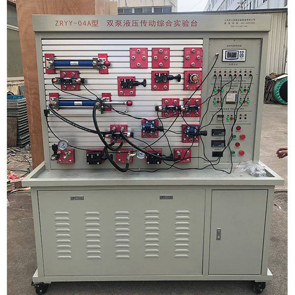


| Experiment bench | Welded steel structure | 1 set |
| Universal wheel | With self-locking function; roller bearing | 4 |
|
Special pump station control system (1 set) |
Open with leakage protection | 1 |
| AC contactor | 2 | |
| 220V relay | 2 | |
| emergency button | 1 | |
| Button (red, green) | 2 each | |
| indicator light | 2 sucks | |
| emergency button | 1 each | |
| Variable vane pump + drive motor |
Rated displacement: 12ml/r Rated pressure: 7MPa Rated power: 1.5kw Rated voltage: AC380V |
1 set |
| Fixed vane pump + drive motor |
Rated displacement: 12ml/r Rated pressure: 7MPa Rated power: 2.2kw Rated voltage: AC380V |
1 set |
| tank | Rated volume 100L | 1 |
| *r filter | HS-1163 | 1 |
| oil suction filter | MF-04 | 1 |
| Oil temperature and oil level gauge | LS-3 | 1 |
| oil pipe | 1.5 m | 2 pieces |
| Double acting hydraulic cylinder assembly |
Component model: MOB-40*150-LB Maximum stroke: 150mm Bore size 40 |
2 |
| Throttle valve stop valve assembly | Component model: DV12-1-10B/ | 2 |
| Relief valve (direct-acting) components |
Component model: DBDH6P10B/100 Component model: FQ-DH6P-2F |
2 |
| Relief valve (pilot type) components |
Component model: DB10-1-30B/315 Component model: FQ-DB10-3F |
1 |
| One-way speed regulating valve assembly |
Component model: 2FRM5-31B/15QB Component model: FQ-2FRM5-2F |
1 |
| Pressure reducing valve assembly |
Component model: DR10-1-30B/100Y Component model: FQ- DR10-2F |
1 |
| Two-position four-way solenoid valve assembly |
Component model: 4WE6C61B/CG24N9Z5L Component model: FQ-4WE6C-3F |
2 |
| Three-position four-way solenoid directional valve (O) components |
Component model: 4WE6E61B/CG24N9Z5L Component model: FQ-4WE6E-3F |
1 |
| Three-position four-way solenoid directional valve (M) components |
Component model: 4WE6G61B/CG24N9Z5L Component model: FQ-4WE6G-3F |
1 |
| Four-way components | Component model: FQ-4T-3F | 2 |
| Glycerin pressure gauge components | Component model: FQ-10MP a-1F-1M | 2 |
| High pressure oil hose assembly | Component model 10-1-25.6MP a-2M-0.7 | 5 sticks |
| High pressure oil hose assembly | Component model 10-1-25.6MP a-2M-1.0 | 10 sticks |
| Hydraulic valve transition base plate | A special base plate for hydraulic valves is installed on the valve | 20 yuan |
| Quick change connector male connector | Open and close hydraulic quick connector | 90 pieces |
| Quick change connector female connector | Open and close hydraulic quick connector | 56 |
| Dosing pump oil inlet assembly | 1 | |
| Dosing pump pressure regulating component | DB10-1-30B/315 | 1 |
| Variable pump oil inlet assembly | 1 | |
| Variable pump pressure regulating component | DB10-1-30B/315 | 1 |
| System oil return components | 1 | |
| Hydraulic oil | 32# anti-wear hydraulic oil | 60 liters |
| PLC input and output module |
Component model: FQ-PLC-IN/OUT PLC: Mitsubishi FX1S-20MR 20 points |
1 set |
| Proximity switch | DC24V two-wire system | 4 |
| Special bracket for proximity switch | Aluminum profiles, professional mold making | 4 sets |
| PLC programming cable | 1 | |
| Power strip | AC250V three holes | 1 |
| Product manual | Instructions, instructions | 1 volume |
| Essential tools for equipment m*ntenance |
1 set of hexagonal wrenches (9 pieces), 1 each of screwdrivers "+" and "-", 1 movable wrench 12 inches, 1 center spanner 17-19 19-22, 1 each, 1 needle-nose pliers |
1 set |
 Wechat scan code follow us

24-hour hotline+86 18916464525

Phone18916464525
ADD:Factory 414, District A, No. 6, Chongnan Road, Songjiang Science and Technology Park, Shanghai ICP: Sitemap