Shanghai Daiyu Education Equipment Manufacturing Co., Ltd.
Language:


| serial number | name | model | quantity | Remark |
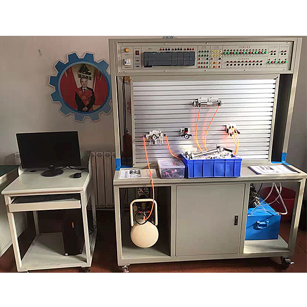
| 1 | Tr*ning table | 1 piece | ||
| 2 | Tr*ning platform | 1 set | ||
| 3 | computer cart | 1 piece | Optional | |
| 4 | PLC host module | FX1S-20MR | 1 piece | Optional |
| 5 | Power module | 1 piece | ||
| 6 | Relay control module | 1 piece | ||
| 7 | PLC control button module | 1 piece | Optional | |
| 8 | Double-acting cylinder (with stroke impact block) | Transparent components | 2 | |
| 9 | Two-position two-way solenoid directional valve | Transparent components | 1 | |
| 10 | Two-position four-way solenoid directional valve | Transparent components | 2 | |
| 11 | Three-position four-way solenoid directional valve (O type) | Transparent components | 1 | |
| 12 | Three-position four-way solenoid directional valve (H type) | Transparent components | 1 | |
| 13 | Three-position four-way solenoid directional valve (M type) | Transparent components | 1 | |
| 14 | Spring return cylinder | Transparent components | 1 | |
| 15 | Pressurized cylinder | Transparent components | 1 | |
| 16 | Auxiliary fuel tank | Transparent components | 1 | |
| 17 | One-way valve | Transparent components | 2 | |
| 18 | Hydraulic control check valve | Transparent components | 2 | |
| 19 | Relief valve (direct acting) | Transparent components | 2 | |
| 20 | Relief valve (pilot type) | Transparent components | 1 | |
| twenty one | Throttle valve (direct acting) | Transparent components | 1 | |
| twenty two | Control Valve | Transparent components | 2 | |
| twenty three | sequence valve | Transparent components | 2 | |
| twenty four | Pressure reducing valve | Transparent components | 1 | |
| 25 | Two-position four-way stroke directional valve | Transparent components | 1 | |
| 26 | Three-position five-way manual directional valve | Transparent components | 1 | |
| 27 | pressure relay | Transparent components | 1 | |
| 28 | pressure gauge | Transparent components | 3 | |
| 29 | tee joint | Transparent components | 7 | |
| 30 | Four-way connector | Transparent components | 3 | |
| 31 | Limit switch | 4 | ||
| 33 | Transparent hydraulic hose | 20 meters | ||
| 34 | oil pan | 1 | ||
| 35 | tank | 1 | ||
| 36 | *r filter | 1 | ||
| 37 | oil suction filter | 1 | ||
| 38 | Oil temperature and level gauge | 1 | ||
| 39 | Pump unit | 1 set | ||
| 40 | L-HL46 hydraulic oil | 30kg | ||
| 41 | Solenoid valve universal connection line | 3 items | ||
| 42 | Pressure relay plug wire | 1 item | ||
| 43 | Programming cable (Mitsubishi) | 1 item | ||
| 44 | tool | 1 set | ||
| 45 | Quick oil connector | 5 | ||
| 46 | oil plug | 5 | ||
| 47 | Hydraulic transmission tr*ning instructions | 1 volume | ||
| 48 | PLC programming software, programs, configuration software | CD | 1 plate | |
| 49 | Hydraulic and pneumatic transmission design and control virtual simulation software | 3dUnity production | 1 set |
| serial number | name | model | quantity | Remark |
| 1 | PLC host module | FX1S-20MR | 1 piece | Optional |
| 2 | Power module | 1 piece | ||
| 3 | Relay control module | 1 piece | ||
| 4 | PLC control button module | 1 piece | Optional | |
| 5 | Silent *r compressor | 1 set | ||
| 6 | single acting cylinder | QGX25ⅹ100 | 2 | |
| 7 | Double acting cylinder | QGX25ⅹ100 | 1 | |
| 8 | Rotating cylinder | 1 | ||
| 9 | triple piece | AC2000 | 1 | |
| 10 | Pressure reducing valve (with pressure gauge) | AR2000 | 1 | |
| 11 | Manual reversing valve | H210—08 | 1 | |
| 12 | Single solenoid directional valve (two-position three-way) normally open | 3V210-8 | 1 | |
| 13 | Single solenoid directional valve (two-position three-way) normally closed | 3V210-8 | 1 | |
| 14 | Single solenoid directional valve (two-position five-way) | 4V210-8 | 2 | |
| 15 | Double solenoid directional valve (two-position five-way) | 4V220-8 | 1 | |
| 16 | Double solenoid directional valve (three-position five-way) | 4V230-8 | 1 | |
| 17 | Single gas directional valve (two-position five-way) | 4A210—08 | 2 | |
| 18 | Two-gas directional valve (two-position five-way) | 4A220—08 | 2 | |
| 19 | Stroke valve (machine control) | MOV-2 | 1 | |
| 20 | Stroke valve (button) | MOV-3 | 1 | |
| twenty one | Stroke valve (button with lock) | MOV-3A | 1 | |
| twenty two | Or gate type shuttle valve | ST-02 | 2 | |
| twenty three | Quick exhaust valve | 1/4QE—02 | 2 | |
| twenty four | One-way throttle valve | RE—02 | 2 | |
| 25 | One-way throttle valve | JSC601 | 1 | |
| 26 | One-way valve | 1/4 | 2 | |
| 27 | sequence valve | 1 | ||
| 28 | Calmness | 1 | ||
| 29 | trachea | PU6ⅹ4 | 20 meters | |
| 30 | Stroke switch (mounted on the cylinder) | 2 | ||
| 31 | Microcontroller, PLC programmable design and control virtual simulation software | 3dunity production | 1 set | |
| 31 | Programming cable (adapter) | Mitsubishi | 1 item | |
| 32 | Allen wrench | 3 handfuls | ||
| 33 | screwdriver | 2 handfuls | ||
| 34 | Scissors | 1 handful | ||
| 35 | movable wrench | 1 handful | ||
| 36 | Needle nose pliers | 1 handful | ||
| 37 | Muffler (small) | 1/8 | 2 | |
| 38 | Muffler (large) | 3/8 | 2 | |
| 39 | Tee (T-shaped tee) | Ø6 | 4 | |
| 40 | Tee (Y-shaped reducing tee) | Ø8—Ø6 | 2 | |
| 41 | four links | Ø6 | 2 | |
| 42 | L type (threaded two-way) | 601 | 2 | |
| 43 | L type (threaded two-way) | 602 | 2 | |
| 44 | Air hole plug | Ø6 | 20 pieces | |
| 45 | Pneumatic tr*ning guide | 1 volume | ||
| 46 | PLC programming software, programs, configuration software | CD | 1 plate | Optional |
 Wechat scan code follow us

24-hour hotline+86 18916464525

Phone18916464525
ADD:Factory 414, District A, No. 6, Chongnan Road, Songjiang Science and Technology Park, Shanghai ICP: Sitemap