Shanghai Daiyu Education Equipment Manufacturing Co., Ltd.
Language:


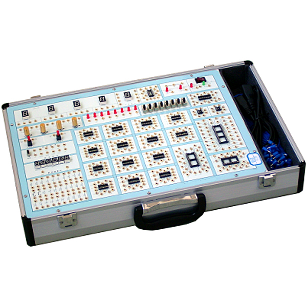


Digital circuit learning machine, the host provides a variety of signal sources; characters are printed on the front and components are installed on the back. All signal source frequency meters and other circuits are composed of CPLD chips and double panels. All components are made of high-quality products, making the entire The quality of the machine is improved. Since the components are all installed on the back, it can effectively reduce and avoid the possibility of human damage. The characteristics of this machine are: easy to use, durable, flexible experimental items, and can facilitate various digital simulation experiments. This learning machine is suitable for electronic technology teaching in colleges and universities and various vocational and technical schools.
1. System composition
(1) Structure: aluminum alloy frame, fireproof materials, environmentally friendly glue, handles, reliable quality, sturdy and durable.
(2) Power supply: AC input: 220V±10%, 50HZ, power switch with LED light indication
DC output: ±12V/200mA, 5V/2A
Each of the above outputs has overcurrent, short circuit, overheating and other protection measures, automatic recovery function, and internal resistance of less than 0.1 ohm.
(2) 2 sets of manual single pulse circuits: can output two positive and negative pulses at the same time, and the pulse amplitude is TTL level.
(3) A group of continuous pulses, the output is TTL level:
Fixed frequency pulse source: 1HZ, 1KHZ, 10KHZ, 100KHZ, 1MHZ;
(4) Six-digit high-precision digital frequency meter, measurement range: 0-9.9999MHZ error <1HZ (designed by CPLD chip)
(5) Logic level input and display:
A. 12-bit independent logic level switch: can output "0" and "1" levels (positive logic).
B. 12-bit logic level display circuit composed of red LED and drive circuit.
(6) Digital tube display:
A. 4-digit BCD code decoding display circuit composed of eight-segment LED digital tubes;
B. 1-digit eight-segment LED digital tube with all pins lead out for digital tube experiments.
(7) 4-way timing generator and start-stop control circuit.
(8) 21 round hole sockets of 8 cores, 14 cores, 16 cores, 20 cores, 28 cores, etc., which can meet various IC chips
(9) 4 potentiometers of each resistance value.
(10) The component area provides 30 resistors and capacitors of common specifications, and provides two sets of component sockets, which can facilitate the insertion of resistors, capacitors, diodes, transistors and other components, allowing users to freely build circuits.
(11) Provide det*led experimental instructions, WORD electronic documents, etc.
(12) Teacher teaching design system: This system is in apk format and can be used on PC or mobile. This system can set faults manually or automatically. This system can be selected through the green box in the circuit diagram. Fault points can be set manually (up to 39 fault points can be set), or the system can automatically set one fault point at random, two fault points at random, three fault points at random, four fault points at random, and five fault points at random. Set each fault point. This system has toolbox, component library, magnifying glass, circuit diagram and other functions. You can choose a multimeter for detection through the toolbox, select appropriate components through the component library, and clearly understand each component and circuit through the magnifying glass. . This system allows students to understand the working principle and circuit structure of the motor star-delta start control circuit through the setting of faults in the motor star-delta start control circuit and various investigations.
2. Recommended experimental projects
1. Parameter testing and use of TTL integrated logic gates
2. Testing of CMOS integrated logic gates
3. Logic function experiment of gate circuit
4. Testing of commonly used combinational logic functional devices
5. Half adder, full adder and logic operation experiment
6. Seven-person voting circuit and blood type detection circuit
7. Functional test of RS trigger
8. JK, D flip-flop logic function and m*n parameter testing
9. Three-state output starter and latch
10. Asynchronous binary counter experiment
11. Synchronous binary counter experiment
12. Functional test of shift register
13. Counting, decoding and display circuit experiments
14. 555 integrated circuits and applications
15. Waveform generation and monostable trigger
16. Design of sequence detector
17. D/A digital-to-analog converter
18. A/D analog-to-digital converter
19. Traffic light controller with manual intervention
20. Digital electronic clock design
21. Digital frequency meter
22. Car t*llight control experiment
Recommended products: Electrician tr*ning bench
 Wechat scan code follow us

24-hour hotline+86 18916464525

Phone18916464525
ADD:Factory 414, District A, No. 6, Chongnan Road, Songjiang Science and Technology Park, Shanghai ICP: Sitemap