Shanghai Daiyu Education Equipment Manufacturing Co., Ltd.
Language:


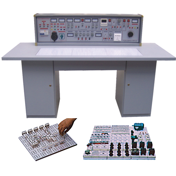


The experimental bench has relatively complete safety protection measures and relatively complete functions. The center of the experimental table is equipped with a universal circuit board. The circuit board is made of injection molding. The surface is porous and forms a set of interconnected jacks. The component boxes can be assembled and inserted into the experimental circuit at will. It is intuitive and the box cover is printed with a color that will never fade. Component symbols, lines are clear and beautiful. The box body and lid adopt a more scientific clamping structure, which is convenient for m*ntenance and disassembly. The components are placed in the left and right cabinets under the experimental table, which greatly improves the management level and planning level, and greatly reduces the teacher's experimental preparation work.
2. Experimental bench and operating table structure:
|
1. Experimental bench shell size: 123×35×20cm 2. Three phase fuse 3. Three-phase power input indicators 4. M*n switch: m*n switch of the power supply of the experimental bench, with leakage and overload protection 5. Test button: Test the leakage function of the leakage switch 6. Power input indicator 1 7. 3 power output indicators (red, green and yellow) 8. AC voltmeter: Indicates output line voltage 9. Voltage conversion switch: Used in conjunction with a voltmeter to monitor the size and symmetry of the output line voltage 10. 5 terminal blocks: unit A three-phase four-wire and ground wire output 11. Ammeter W phase current output indication 12. O/I switch: three-phase four-wire power output control (Improve safety factor) 13. 2 terminal blocks: Unit B AC low-voltage power output 14. Electric meter (2A): Unit B AC current indication 15. Knob: Unit B 3-24V AC low voltage selection output 16. Switch: C unit dual-channel DC regulated power supply switch 17. Knob: C unit dual-channel I channel steady flow adjustment 18. Knob: C unit dual-channel II channel steady flow adjustment 19. 2 terminal blocks: Unit C Ⅰ DC regulated output 20. Insurance holder: C unit dual-channel regulated power supply fuse twenty one. 4 electric meters: dual-channel regulated power supply voltage and current indication twenty two. Terminal block: D unit DC 5V regulated output twenty three. Electric meter: D unit current 0.5V output indication twenty four. Switch 1: Controls various low-voltage alternating current and signal sources 25. Switch 2: Control the AC and DC voltage-regulated power supply of unit E 26. Electric meter: E unit AC voltage output indication |
27. 4 terminal blocks: E unit AC and DC output ports 28. Knob: E unit 0~240V voltage adjustment 29. Socket: G unit 220V output socket 30. Knob: Audio power amplifier volume adjustment 31. 2 terminal blocks: audio signal input 32. Button: Single pulse enable switch 33. 3 terminal blocks: single pulse output port 34. Electric meter: function generator sine wave output voltage indication 35. Knob: coarse adjustment of three-level attenuation amplitude of sine wave output 36. Knob: Sine wave output port 37. Terminal block: sine wave output port 38. Knob: Rectangular wave output amplitude adjustment 39. Terminal block: triangle wave output port 40. Knob: Function signal generator frequency fine adjustment 41. Terminal block: rectangular wave output port 42. Knob: Function signal generator five-level frequency coarse adjustment 43. Electric meter: function generator output frequency indication 45. Experimental desktop size: 160×70cm 46. Universal circuit board: specification 35×90cm, component boxes can be assembled and inserted on it for experiments 47. Storage board: Place component boxes 48. Left storage cabinet: place storage board (with door lock) 49. Drawer: place commonly used tools 50. Right storage cabinet: place storage board (with door lock) |
3. M*n technical indicators of the experimental bench:
1. Input working power: single-phase input
2. Output power and signal
Unit A: single-phase 220V output
Unit B: AC 3, 6, 9, 12, 15, 18, 24V
Unit C: Dual-channel constant-current regulated power supply (with overload and short-circuit protection functions), both output voltages are 0~30V, built-in relay automatically shifts gears, and is continuously adjusted by a multi-turn potentiometer. It is easy to use and outputs the maximum current. It is 2A and has preset current limiting protection function.
Voltage stability: <10-2 Load stability: <10-2 Ripple voltage: <5mv
Unit D: DC regulated voltage 5V, current 0.5A
Unit E: AC and DC voltage continuously adjustable from 0 to 240V, current 2A
Unit F: 220V voltage output for external instruments.
3. Single pulse source: a p*r of positive and negative pulses can be output each time
4. Function signal generator (sine wave, triangle wave, rectangular wave)
① Frequency range: 5HZ-550KHZ is divided into five frequency bands
② Frequency indication: read directly from the HZ meter
③Voltage output range: sine wave: 5HZ-250KHZ>4.5V, 250KHZ-550KHZ>3.5V
Three levels of attenuation: 0db, 20db, 40db with continuous fine adjustment
Rectangular wave: 5HZ-250KHZ>4.5V, 250KHZ-550KHZ>3.5V, the amplitude is continuously adjustable
Triangular wave: 5HZ-550KHZ>1V
5. Audio power amplifier: The input audio voltage is not less than 10mv, the output power is not less than 1W, the volume is adjustable, and there is a speaker inside, which is used for amplifier circuit amplification and can also be used as a signal tracing instrument.
6. Insulation resistance: >5MΩ
7. Leakage protection: leakage action current ≤30mA
4. Structure and equipment
1. Experimental table: Student experimental table, one with two seats, table dimensions: 160×70×80cm. A universal porous circuit board is placed in the center of the table. According to the experimental circuit, any component box can be inserted on it to form an experimental circuit. The internal components are clear at a glance. The box cover is printed with component symbols that will never fade. The lines are clear and beautiful. The box cover and box body adopt a press-fit type. Structure, easy to disassemble and m*nt*n. Each table is equipped with a rubber plate to protect the general plug-in board and the desktop (if you need to place motors, welding, etc. on the table). Under the table are component storage cabinets for placing experimental components.
2. Equipment: DC ammeter, multimeter, resistors, potentiometers, capacitors required for experiments, transformers, diodes, transistors, field effect tubes, integrated thyristors, sensors , logic level displays and logic level switches and other component units box (components have been installed in the unit box).
5. Experimental projects
|
1. Characteristics and detection of crystal diodes 2. Transistor input and output characteristics 3. Low frequency small signal voltage amplifier 4. Directly coupled two-stage amplifier 5. RC coupled two-stage amplifier 6. The impact of negative feedback on amplifier performance 7. Transformer coupled push-pull power amplifier 8. Complementary Symmetrical Push-Pull Power Amplifier (OTL) 9. Single phase half wave rectifier 10. Single phase full wave rectification 11. Single phase bridge rectifier 12. Single-phase bridge rectifier filter 13. Single junction transistor characteristics 14. Unijunction transistor trigger circuit 15. Simple test of thyristor and controllable rectifier circuit 16. Field effect tube test 17. Series regulated voltage 18. Research on differential amplifier circuit 19. Testing of integrated operational amplifier parameters 20. Integrated op amp subtraction circuit twenty one. Integrated op amp adding circuit twenty two. Integrated operational amplifier integrating circuit Surface experiments can also be completed using the above 44 experimental components. 45. PN junction unidirectional conductive characteristics 46. Measurement circuit of three-power ICBO 47. Measurement circuit of triode ICEO 48. Transistor current amplification 49. VA characteristics of triode 50. Single-stage small-signal voltage amplification with load 51. Voltage negative feedback bias circuit 52. Voltage-divided current negative feedback bias circuit 53. Stabilizing the operating point with a thermistor 54. Using diodes to stabilize the operating point 55. Analyze the influence of Ce on low frequency characteristics 56. Common base amplifier experimental circuit 57. Common collector amplification experimental circuit 58. Common source basic amplifier circuit 59. Field effect tube self-cont*ned bias amplifier circuit 60. Field effect transistor voltage dividing self-bias circuit 61. Field effect transistor common dr*n circuit 62. Field effect transistor common gate circuit 63. Single-tube resistance-capacitance amplifier circuit 64. Basic DC amplifier circuit 65. Use a resistor to increase the emitter potential of the subsequent stage 66. Use a voltage regulator tube to increase the emitter potential of the rear stage 67. Transformer coupled amplifier circuit 68. Class A power amplifier circuit 69. Class B power amplifier circuit 70. Series current negative feedback 71. Series voltage negative feedback circuit 72. Parallel voltage negative feedback circuit 73. Parallel current negative feedback circuit 74. Negative feedback in two-stage amplifier circuit 75. Emitter output circuit 76. Bootstrap emitter output circuit 77. Use capacitors to attenuate high-frequency voltages 78. Use negative feedback to eliminate self-oscillation 79. battery monitoring circuit 80. Field effect transistors and transistors form an amplifier circuit 81. PNP-NPN direct coupling amplifier circuit 82. Common base cascode amplifier circuit 83. Transistor switching function 84. Liquid level photoelectric control 85. Simple temperature control circuit 86. Analog light-controlled simple street light automatic switch circuit 87. RC Phase Shift Oscillator 88. Double T frequency selection network 89. Oscillator composed of double T frequency selective network 90. Transformer feedback oscillation circuit 91. Field effect transistor transformer feedback oscillation circuit 92. Anti-theft alarm circuit 93. Series crystal oscillator circuit 94. complementary audio oscillator 95. alarm sounder 96. Music doorbell circuit 97.Electronic alarm circuit 98. The basic form of differential amplifier circuit 99. Electronic doorbell circuit 100. Quasi-complementary symmetrical circuit 101. Three-tube OTL complementary symmetrical circuit 102. Long t*l differential amplifier circuit 103. Differential input single-ended output 104. Single-ended input double-ended output 105. Single-ended input single-ended output 106. Dual power supply long t*l differential amplifier circuit 107. Differential amplifier experimental circuit 108. Differential amplifier circuit measures with constant current source 109. Ironic analysis of single-ended output differential amplifier circuit 110. flasher circuit 111. Basic connection method of operational amplifier 112. Current differential operational amplifier is used as AC proportional amplification 113. Simple measurement method of Vos 114. A simple measurement method for Aos 115. A simple measurement method of Aod 116. Simple test of common mode rejection ratio Cmrr 117. Simple test of maximum common mode input voltage UIcm 118. Yopp's simple test 119. SR measurement method 120. Basic non-inverting amplification connection method 121. LC oscillator composed of op amp 122. Electric heating cup temperature adjustment circuit 123. Lead to the reverse end input zero adjustment measure 124. Lead to the same direction end and input the zero adjustment instruction. 125. In order to prevent the electric value from being too large, 126. Using the base current of the transistor to achieve temperature compensation of Ios 127. Utilizing T-shaped network to improve equivalent feedback resistance 128. Measures to make the complementary tube work in Category A and B to expand the output current 129. Measures to be taken when correcting capacitive loads 130. Inverting input protection measures 131. Non-inverting input protection measures 132. Use voltage regulator tubes to protect devices 133. Protection ag*nst wrong polarity of power supply 134. Instantaneous overvoltage protection when power is on 135. Diode detection circuit 136. Circuit principle of measuring temperature using the temperature coefficient of PN junction 137. Dual diode limiter 138. Basic circuit of inverting op amp 139. Variable ratio magnification 140. Basic circuit of non-inverting op amp 141. Voltage/current conversion circuit 142. Current/voltage conversion circuit |
twenty three. Integrated operational amplifier differential circuit twenty four. Integrated Op Amp Wien Sine Wave Oscillator 25. Capacitive three-point oscillator 26. Inductive three-point oscillator 27. Integrated voltage stabilizing circuit 28. Astable circuits (multivibrators) 29. Schmitt trigger 30. Integrated AND gate logic function test 31. Integrated NOT gate logic function test 32. Integrated OR gate logic function test 33. Integrated NAND gate logic function test 34. Testing of CMOS gate circuits 35. Basic RS flip-flop 36. JK flip-flop 37. D flip-flop 38. Application of 555 time base circuit (square wave generator) 39. binary decimal counter 40. Binary decimal 8421 decoder 41. Adder 42. subtractor 43. Constructing a Monostable Flip-Flop Using Integrated NAND Gates 44. combinational logic circuit
143. voltage follower 144. Differential amplifier basic circuit 145. The differential output of the operational amplifier 146. Inverted input sum operation 147. In-phase input summation operation 148. Two-ended input sum operation 149. Basic integrating circuit 150. EG test leakage resistance p*r integral operation circuit 151. Measures to improve the integration time constant 152. Fast integrating circuit 153. Simulate first-order differential equation circuits 154. Simulate second-order differential equation circuits 155. basic differential circuit 156. Practical Differential Circuits 157. Using indirect methods to obt*n approximate differentials 158. Basic logarithmic operation circuit 159. Using the logarithmic characteristics of transistors to form a logarithmic operation circuit 160. Basic circuit of antilog amplification 161. Vo is proportional to the VxVy circuit 162. Simple zero-crossing comparison circuit 163. Comparator circuit with hysteresis characteristics 164. Double limit comparison circuit 165. Using diodes as upper limit detection amplitude selection circuit 166. Double limit three-state comparison circuit 167. Lower limit detection amplitude selection circuit 168. Basic sampling protection circuit 169. RC passive network terminal low-pass filter circuit 170. The filter circuit is connected to the non-inverting input terminal of the component 171. The filter circuit is connected to the inverting input of the component 172. Simple second-order RC filter circuit 173. Typical RC active filter circuit 174. Two-stage active filter circuit 175. Multi-channel feedback secondary active filter circuit 176. Typical second-order high-pass active filter circuit 177. Basic bandpass filter circuit 178. Typical bandpass filter circuit 179. Band stop filter composed of double T network 180. Output limiting inverter 181. Practical Difference Op Amp 182. Square wave oscillator circuit 183. Resistor-capacitor phase shift trigger circuit 184. Electric heating mattress temperature control device 185. Adjustable width rectangular wave generator 186. Simple sawtooth wave generator 187. Amplitude and frequency adjustable sawtooth wave generator 188. Commonly used drawing circuits for single-phase bridge rectifiers 189. Maximum reverse peak voltage of full-wave rectifier circuit 190. Capacitor filter circuit 191. Capacitive filter with resistive load 192. Full wave rectifier capacitor filter circuit 193. RC filter circuit 194. Multi-stage RC filter circuit 195. Basic LC filter circuit 196. T-shaped filter circuit 197. Double voltage rectifier circuit 198. Triple voltage rectifier circuit 199. Basic voltage regulator circuit 200. Basic regulating tube voltage stabilizing circuit 201. Voltage stabilizing circuit with amplification link 202. Adjustment tube current stabilizing circuit 203. electronic filter 204. Series voltage stabilizing circuit 205. Parallel voltage stabilizing circuit 206. electronic hypnosis device 207. Three-terminal integrated voltage stabilizing circuit 208. Positive power output adjustable integrated voltage stabilizing circuit 209. Single-phase full-wave controllable rectification 210. Silicon voltage regulator circuit 211. Single-phase half-wave controllable rectification 212. Single-phase bridge semi-controlled rectifier 213. Principle of silicon rectifier for charging 214. Effect of inductive load on thyristor 215. Thyristor trigger conduction test 216. Back electromotive force load thyristor circuit 217. Simple electronic voltage regulation circuit 218. Test the single-junction tube partial pressure ratio n 219. Single junction oscillator circuit 220. Single junction tube trigger application circuit 221. Diode AND gate circuit 222. Transistor "OR" gate circuit 223. visualization with logic 224. or logical visualization 225. illogical visualization 226. Transistor "NOT" Gate 227. Transistor NAND gate 228. Transistor "NOR" gate 229. Three-barrel bistable circuit 230. triode monostable circuit 231. triode multivibrator circuit 232. Set trigger circuit 233. emitter coupled bistable 234. Symmetric multivibrator 235. ring multivibrator 236. Differential monostable circuit 237. Integrated Schmitt circuit 238. Square wave generator 239. single pulse circuit 240. continuous pulse generator |
configuration list:
|
Component name |
model |
quantity |
Remark |
|
resistance |
5.1Ω |
2 |
1/2W |
|
resistance |
51Ω |
1 |
1/2W |
|
resistance |
100Ω |
3 |
1/8W |
|
resistance |
150Ω |
1 |
1/8W |
|
resistance |
200Ω |
1 |
1/8W |
|
resistance |
300Ω |
2 |
1/8W |
|
resistance |
470Ω |
1 |
1/8W |
|
resistance |
510Ω |
2 |
1/8W |
|
resistance |
820Ω |
2 |
1/8W |
|
resistance |
1K |
3 |
1/8W |
|
resistance |
1.5K |
1 |
1/8W |
|
resistance |
2K |
2 |
1/8W |
|
resistance |
2.4K |
3 |
1/8W |
|
resistance |
2.7K |
1 |
1/8W |
|
resistance |
3.3K |
3 |
1/8W |
|
resistance |
3.9K |
1 |
1/8W |
|
resistance |
4.7K |
2 |
1/8W |
|
resistance |
5.1K |
1 |
1/8W |
|
resistance |
6.8K |
2 |
1/8W |
|
resistance |
10K |
4 |
1/8W |
|
resistance |
13K |
1 |
1/8W |
|
resistance |
20K |
2 |
1/8W |
|
resistance |
39K |
1 |
1/8W |
|
resistance |
51K |
1 |
1/8W |
|
resistance |
100K |
2 |
1/8W |
|
resistance |
200K |
1 |
1/8W |
|
resistance |
1M |
1 |
1/8W |
|
resistance |
10M |
1 |
1/8W |
|
Potentiometer |
470Ω |
1 |
1/2W |
|
Potentiometer |
1K |
2 |
1/2W |
|
Potentiometer |
10K |
2 |
1/2W |
|
Potentiometer |
22K |
1 |
1/2W |
|
Potentiometer |
100K |
1 |
1/2W |
|
Potentiometer |
470K |
1 |
1/2W |
|
electrolytic capacitor |
1uF |
1 |
16V |
|
electrolytic capacitor |
10uF |
3 |
16V |
|
electrolytic capacitor |
47uF |
3 |
16V |
|
electrolytic capacitor |
220uF |
1 |
35V |
|
electrolytic capacitor |
470uF |
1 |
35V |
|
ceramic capacitor |
300P |
1 |
63V |
|
ceramic capacitor |
1000P |
2 |
63V |
|
ceramic capacitor |
0.01uF |
2 |
63V |
|
ceramic capacitor |
0.1uF |
1 |
63V |
|
ceramic capacitor |
0.47uF |
1 |
63V |
|
audio input transformer |
1 |
||
|
audio output transformer |
1 |
||
|
transformer |
220/6V.6V |
1 |
8W |
|
Inductor |
8Ω |
1 |
|
|
Inductor |
390UH |
1 |
|
|
diode |
4007 |
4 |
|
|
diode |
2AP9 |
1 |
|
|
led |
2 |
||
|
Zener diode |
2CW54 |
2 |
|
|
Zener diode |
2CW76 |
1 |
|
|
crystal oscillator |
10M |
1 |
|
|
field effect transistor |
3DJ6 |
1 |
|
|
Single knot tube |
BT33 |
1 |
|
|
Thyristor |
KP1 |
2 |
|
|
triode |
3DG6 |
2 |
|
|
triode |
3DG12 |
1 |
|
|
triode |
3AX31 |
2 |
|
|
triode |
3DA1 |
1 |
|
|
Three-terminal voltage stabilization |
7805 |
1 |
|
|
Indicator light (signal light) |
6V 0.1A |
1 |
|
|
switch |
4 |
||
|
trumpet |
8Ω/0.2W |
1 |
|
|
relay |
6V |
1 |
|
|
music integration |
4V |
1 |
|
|
Level switch and logic level indication |
1 |
||
|
Integrated seat |
14 feet |
2 |
|
|
Integrated seat |
16 feet |
1 |
|
|
Integrated op amp |
UA741 |
2 |
|
|
timer |
NE555 |
1 |
|
|
TTL NAND gate |
74LS00 |
1 |
|
|
TTL NOT gate |
74LS04 |
1 |
|
|
TTL AND gate |
74LS08 |
1 |
|
|
TTL NAND gate |
74LS20 |
1 |
|
|
TTL OR gate |
74LS32 |
1 |
|
|
decoder |
74LS42 |
1 |
|
|
TTL flip-flop |
74LS74 |
1 |
|
|
seven-segment decoder |
74LS247 |
1 |
|
|
full adder |
74LS283 |
1 |
|
|
CMOS NOR gate |
CD4002 |
1 |
|
|
Gongyang digital device |
546R |
1 |
|
|
DC meter |
10MA |
1 |
|
|
DC meter |
200MA |
1 |
|
|
DC meter |
1V |
1 |
|
|
DC meter |
15V |
1 |
|
|
DC meter |
±100UA |
1 |
|
|
tool |
|||
|
multimeter |
MF47 |
1 |
|
|
Needle nose pliers |
1 |
||
|
screwdriver |
3 |
||
|
Wire strippers |
1 |
||
|
Connecting line |
several |
||
|
other |
|||
|
Experimental bench |
1 set |
||
|
Experiment table |
1 piece |
||
|
antiseptic leather |
1 piece |
||
|
stool |
2 pictures |
||
If the parts manufacturer discontinues production or is out of stock, we will replace it with parts of equal performance.
 Wechat scan code follow us

24-hour hotline+86 18916464525

Phone18916464525
ADD:Factory 414, District A, No. 6, Chongnan Road, Songjiang Science and Technology Park, Shanghai ICP: Sitemap